Making quick roadway design models for review and public uses
ACECWI Civil 3D workshop 2024
Last updated: 2026-01-06
What's this session about?
- Once you have
- Existing surface data (from previous session)
- 3D design data
- The correct styles and workflows
- You can take visualization and review workflows out of a document and into a modeling world
- This can get very detailed and time-consuming (see any current CGI movie), but it doesn't have to be
- This session is about getting more value out of effort we've already put into the 3D models for WisDOT PS&E deliverables
Software I will use
An Autodesk AEC Collections license will cover it
- Civil 3D 2024
- With current WisDOT package (WisDOT Civil 3D files (wisconsindot.gov))
- InfraWorks 2024
Current WisDOT design data deliverables
- Basically, anywhere with earthwork will have a 3D data requirement for PS&E
- Civil 3D design input for earthwork is the corridor and all of it's inputs
- Design output for construction is corridor feature lines and surfaces built only from those FLs
- Feature lines are built from the same point code connected between corridor sample lines
- The feature lines are the critical piece for construction as they will use them to create construction surfaces (as opposed to design surfaces) in other software
Expanding resource files and workflows to get more value out of 3D data
- While this is great for construction processes, it's not great for visualization (roads that actually look like roads)
- Civil 3D surfaces can only have one color/material assigned to them
- This leads to a lot of surfaces being created for each area of pavement, shoulder, curb, grass, etc. and a lot of work to create and maintain all those surfaces
- It is possible to display corridor links with different materials in the same corridor
- In Civil 3D 2022, WisDOT added codes and styles to make this workflow available to all projects
-
There are limitations, but using these codes and style can generate quick "realistic" models
What you need
- Feature-based link codes (i.e. PaveLn1 instead of Top) in subassemblies
- Items in Code Set Style
- Link codes mentioned above
- AutoCAD Render Materials based on different surfaces (pavement, curb, shoulder, grass)
- Material Area Fill Styles
- If you want different styles applied to different areas,
- Corridor needs to break regions at the material break points.
- You very well may need to add/edit codes in your assemblies to achieve desired results
- HUGE TIP FOR THE DAY: Get used to editing/managing point/link/shape codes in assemblies and code set styles. You will need to for surface building, cross-section labeling, visualization, etc.
EXAMPLE: Project with some concrete and some asphalt
Link code Render Material Material Area Fill Style Pave Vis Mat Pave Asphalt Vis Mat Pave Asphalt PaveLn1 Vis Mat Pave Conc Vis Mat Pave Conc
What you need to know/do to use these
-
If starting with a corridor built before WisDOT Civil 3D 2024
-
To get new styles - Manage tab > Styles panel > Reference
- Delete old ones
- Add C:\WisDOT\Stnd\C3D2024\Templates\Template-ref\group-design.dwt
OK
- To get feature-based link codes - WisDOT Design > Design panel > Assembly - Reset Subassembly Codes (wi.gov) (WARNING: This will eliminate custom codes )
-
- To get ACAD materials - WisDOT Design tab > Design panel > Corridor - Import Code Sets with Render Materials
- Code Set Styles
- Ones that begin wih Color by are the new ones.
- Color by Link gives a different color for each feature (intended for design purposes)
- Color by Top Materials gives a different color for each material (intended for public/non-technical)
- Ones that end in Rendered will display in 3D with Realistic view style
- Ones without Rendered will display in Top view only
- WisDOT code set styles and their uses (nuthin' says luvin' like documentashun)
- Areas where links go to zero-width will not display material areas. There are a few options depending on the scenario:
- Ignore them
- Add sample lines that have link width (reduce the size of empty triangles)
- Clean up the corridor (poor corridor construction methods may yield poor results)
Recommended steps
- Create a new file for visualization purposes from design template
- Set county projection in App menu > Drawing Utilities > Drawing Settings
- Bring in the ACAD materials with WisDOT Design tab > Design panel > Corridor - Import Code Sets with Render Materials
- DREF
- Corridors
- Existing surface
- Anything else you need/want
- XREF (whatever you need/want really)
- Topo
- Proposed pavt
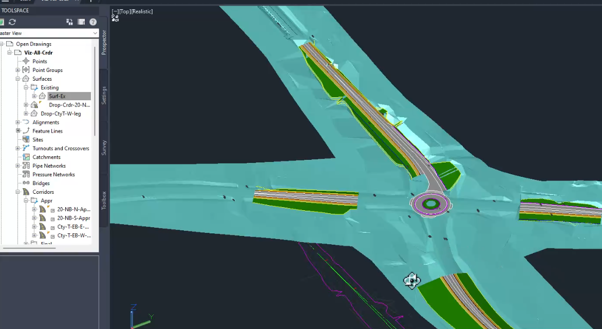
- Set the code set styles to whatever you would like to display
- Make sure the view style is Realistic for 3D viewing
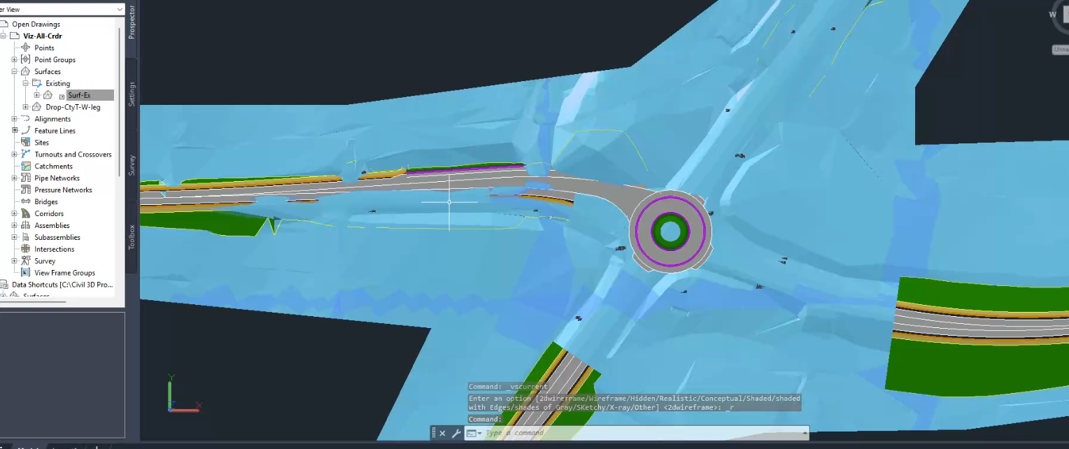
- Areas with earthwork cut will cause problems with visualization in 3D (i.e. the existing ground will cover up proposed work). To fix this:
- Promote Exist surface into the Viz corridor file
- This is generally not recommended and will break the connection to the project Exist surface
- It is necessary to drop existing surface in the footprint of the corridors. This will clean up visualization in Civil 3D and InfraWorks
- Create corridor Top surfaces in your visualization file. WisDOT Design tab > Design panel > Corridor menu > Create Corridor Surfaces
- Rename them to Drop-(corridor name)-Top
- Add an edit with Surface contextual tab > Modify panel > Edit Surface dropdown > Raise/Lower Surface
- Enter an appropriate negative number to get below ditches and cuts
- Paste the Drop surfaces into the promoted Exist surface. This will drop the surface out of the corridor footprints and leave the corridors visible
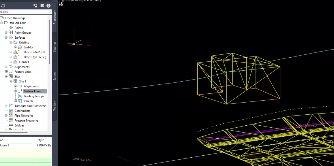
BONUS: Create box "buildings" for 3D display
You may need/want to show 3D objects (walls, buildings, whatever)
- Promote Exist surface into the Viz corridor file
- This can be done with ACAD commands (BOX, CYLINDER, PYRAMID, WEDGE, POLYSOLID)
- This can be done with WisDOT Design tab > Design panel > Surfaces dropdown > Create Wall Surface
- This option has the benefit of working with WisDOT Design tab > Analyze panel > Visibility Check dropdown > Check Intersection Sight Distance
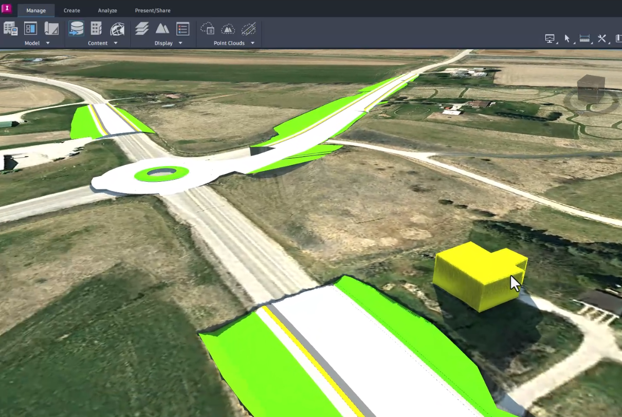
To get to InfraWorks
- Set everything how you want it to look (3D objects) in the visualization file
- Save the file
- Open your existing InfraWorks project
- Manage tab > Content panel > Data Sources > Add Autodesk Civil 3D DWG
- Select the Drop surfaces to add
- Configure Type = Terrain
- Manage tab > Display panel > Surface Layers
- Set the Drop surfaces to Visible and set them above main terrain surface
- Manage tab > Content panel > Data Sources > Add AutoCAD DWG (3D Objects)
- GeoLocation > Coordinate System = County Coordinates
- Type = City Furniture
- This will bring all 3D objects in as they appear at save
-
oh yeah, let's publish this to the web for fun
Limitations
- Corridor areas with no links will not display
- Surfaces can be made in these areas from FeatureLinesFromCorridor and rendered with the appropriate material
- Design surfaces from feature lines and gradings will need to be rendered separately
- You'll need to buy Methods a round of beverages after you get a big promotion impressing everyone with this