Beamguard assemblies
Last updated: 2026-01-06
WisDOT - Beam Guard Assemblies
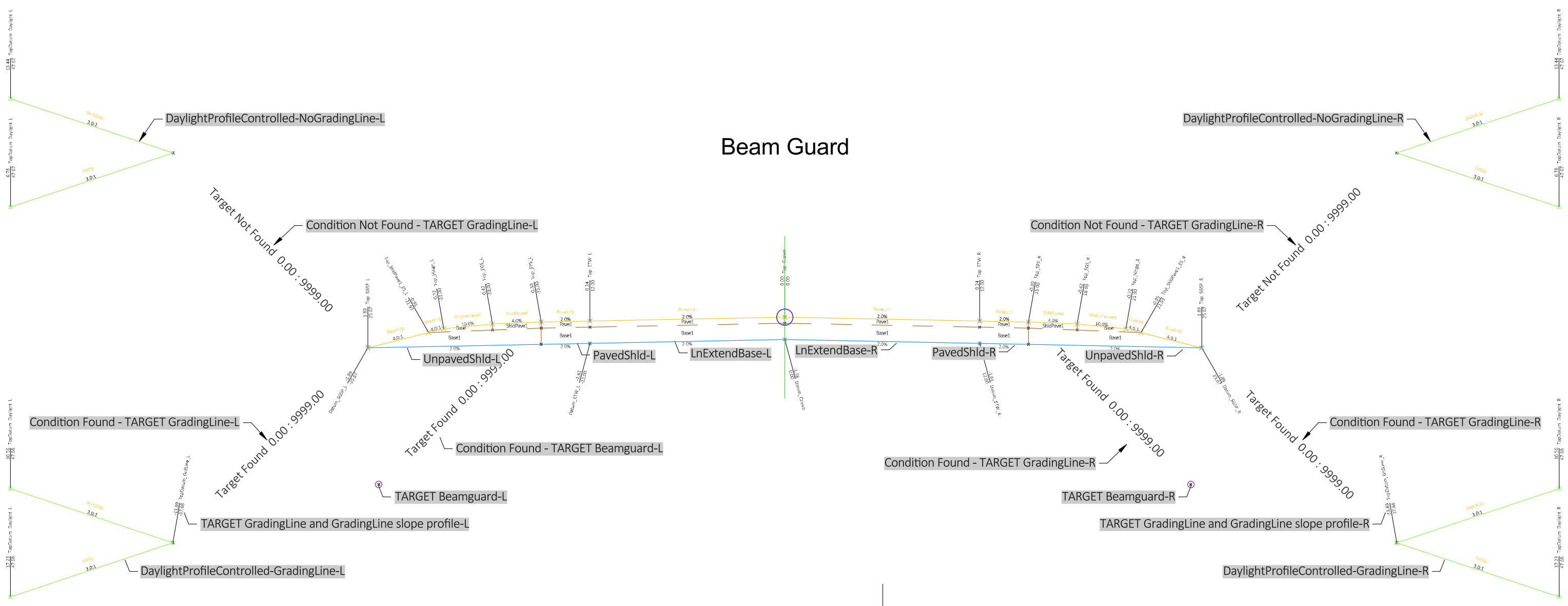
 Beam Guard
Description
This assembly may be used to model a straight run of beam guard or an energy absorbing terminal (EAT) region with associated lane earthwork. Refer to SDD 14B44 for more information on MGS energy absorbing terminals.
The assembly is built to accommodate both left and right side construction. If only one side is desired, the subassemblies may be deleted from the other side. The descriptions in the document are for one side of the assembly. The information is mirrored for the opposite side. This is an example assembly that will likely require modifications to fit specific project needs. Common modifications include:
- Changes to the pavement structure
- Selection of the desired side to model
- Integral paved shoulder vs separate paved shoulder
-
Changes to the daylight subassembly to match project conditions
Construction
The unpaved shoulder on each side is a LnExtendBase - Version: 26.0 subassembly. This is used because there is the potential for 3 top slopes on the rural shoulder in the area of the EAT and the ShldGeneric - Version: 26.2 subassembly only has parameters for two shoulder slopes. The resulting construction parameters are:
-
Paved shoulder slope = PavedShld.Pavement Slope
-
Unpaved shoulder slope to "Edge of Shoulder" in SDD = UnpavedShldr.Paved Shoulder Slope
-
Unpaved shoulder slope "Edge of Shoulder" to "Shoulder Hinge Point" in SDD = UnpavedShldr.Unpaved Shoulder Slope
There are also two conditionals on each side
-
One looks for beam guard alignment targets. If one is found, a generic beam guard block is placed in the section
-
One looks for a GRADELINE alignment targets (see SDD)
-
if none are found, DaylightProfileControlled – Version 26.0 is inserted
-
if one is found, a GRADELINE slope LinkProfileControlled – Version 26.0 is inserted (typically steeper than allowable within clear zone), then DaylightProfileControlled – Version 26.0
-
Warning: Using a GRADELINE slope is not required and often has little impact on the location of the slope intercept of proposed EAT earthwork. It is provided in the assembly to give all options for the design standard detail. Design and construction of EAT earthwork is simpler if it is not used. Engineering judgment needs to applied to appropriate use.
-
-
Baseline
-
Right
-
LnExtendBase-R
-
PavedShld-R
-
UnpavedShld-R
-
Condition Not Found - TARGET GradingLine-R
-
DaylightProfileControlled-NoGradingLine-R
-
-
Condition Found - TARGET GradingLine-R
-
TARGET GradingLine and GradingLine slope profile-R
-
DaylightProfileControlled-GradingLine-R
-
-
Condition Found - TARGET Beamguard-R
-
TARGET Beamguard-R
-
-
-
Left
-
LnExtendBase-L
-
PavedShld-L
-
UnpavedShld-L
-
Condition Not Found - TARGET GradingLine-L
-
DaylightProfileControlled-NoGradingLine-L
-
-
Condition Found - TARGET GradingLine-L
-
TARGET GradingLine and GradingLine slope profile-L
-
DaylightProfileControlled-GradingLine-L
-
-
Condition Found - TARGET Beamguard-L
-
TARGET Beamguard-L
-
-
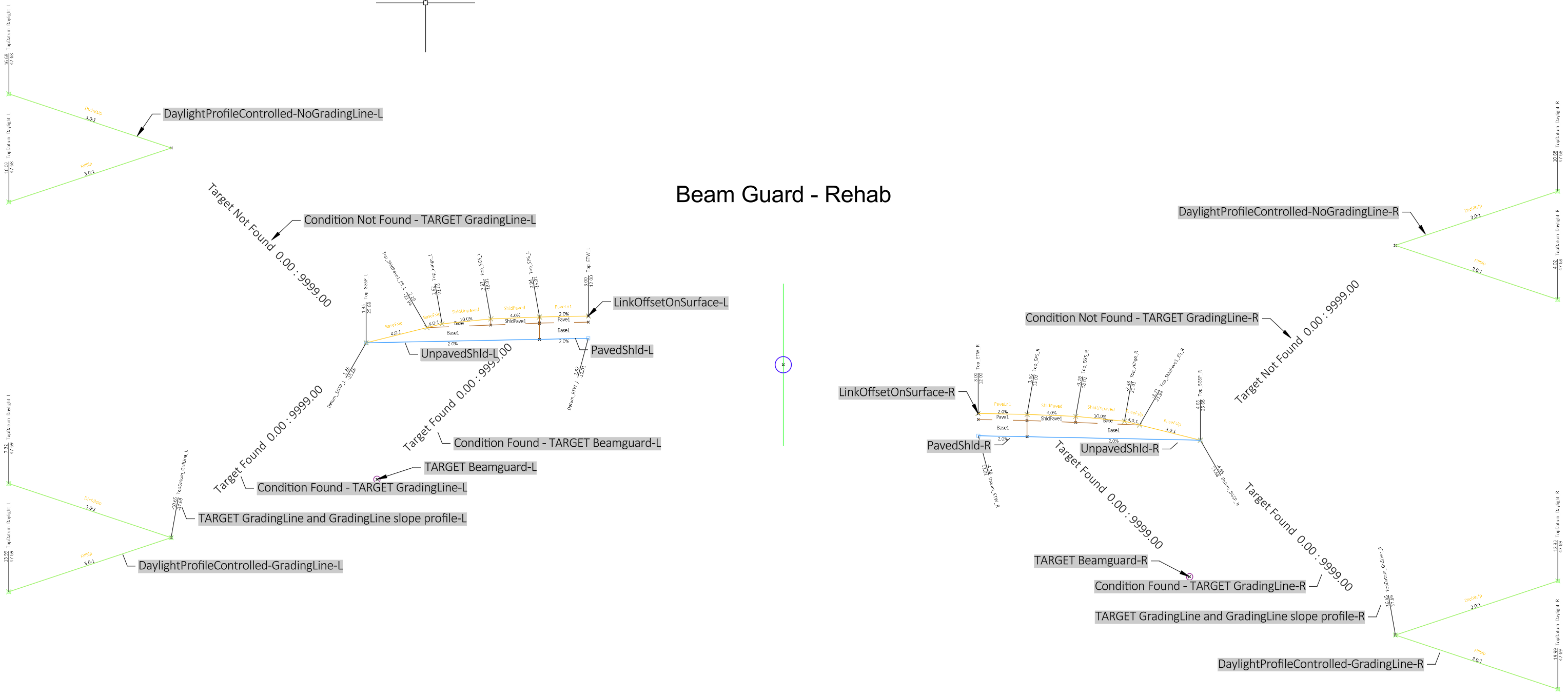
Beam Guard - Rehab
Description
This assembly may be used to model a straight run of beam guard or an energy absorbing terminal (EAT) region where there is only earthwork on the shoulders. Refer to SDD 14B44 for more information on MGS energy absorbing terminals.
The assembly is built to accommodate both left and right side construction. If only one side is desired, the subassemblies may be deleted from the other side. The descriptions in the document are for one side of the assembly. The information is mirrored for the opposite side. This is an example assembly that will likely require modifications to fit specific project needs. Common modifications include:
- Changes to the pavement structure
- Selection of the desired side to model
- Integral paved shoulder vs separate paved shoulder
-
Changes to the daylight subassembly to match project conditions
Construction
The unpaved shoulder on each side is a LnExtendBase - Version: 26.0 subassembly. This is used because there is the potential for 3 top slopes on the rural shoulder in the area of the EAT and the ShldGeneric - Version: 26.2 subassembly only has parameters for two shoulder slopes. The resulting construction parameters are:
-
Paved shoulder slope = PavedShld.Pavement Slope
-
Unpaved shoulder slope to "Edge of Shoulder" in SDD = UnpavedShldr.Paved Shoulder Slope
-
Unpaved shoulder slope "Edge of Shoulder" to "Shoulder Hinge Point" in SDD = UnpavedShldr.Unpaved Shoulder Slope
There are also two conditionals on each side
-
One looks for beam guard alignment targets. If one is found, a generic beam guard block is placed in the section
-
One looks for a GRADELINE alignment targets (see SDD)
-
if none are found, DaylightProfileControlled – Version 26.0 is inserted
-
if one is found, a GRADELINE slope LinkProfileControlled – Version 26.0 is inserted (typically steeper than allowable within clear zone), then DaylightProfileControlled – Version 26.0
-
Warning: Using a GRADELINE slope is not required and often has little impact on the location of the slope intercept of proposed EAT earthwork. It is provided in the assembly to give all options for the design standard detail. Design and construction of EAT earthwork is simpler if it is not used. Engineering judgment needs to applied to appropriate use.
-
-
Baseline
-
Right
-
LinkOffsetOnSurface-R
-
PavedShld-R
-
UnpavedShld-R
-
Condition Not Found - TARGET GradingLine-R
-
DaylightProfileControlled-NoGradingLine-R
-
-
Condition Found - TARGET GradingLine-R
-
TARGET GradingLine and GradingLine slope profile-R
-
DaylightProfileControlled-GradingLine-R
-
-
Condition Found - TARGET Beamguard-R
-
TARGET Beamguard-R
-
-
-
Left
-
LinkOffsetOnSurface-L
-
PavedShld-L
-
UnpavedShld-L
-
Condition Not Found - TARGET GradingLine-L
-
DaylightProfileControlled-NoGradingLine-L
-
-
Condition Found - TARGET GradingLine-L
-
TARGET GradingLine and GradingLine slope profile-L
-
DaylightProfileControlled-GradingLine-L
-
-
Condition Found - TARGET Beamguard-L
-
TARGET Beamguard-L
-
-
-
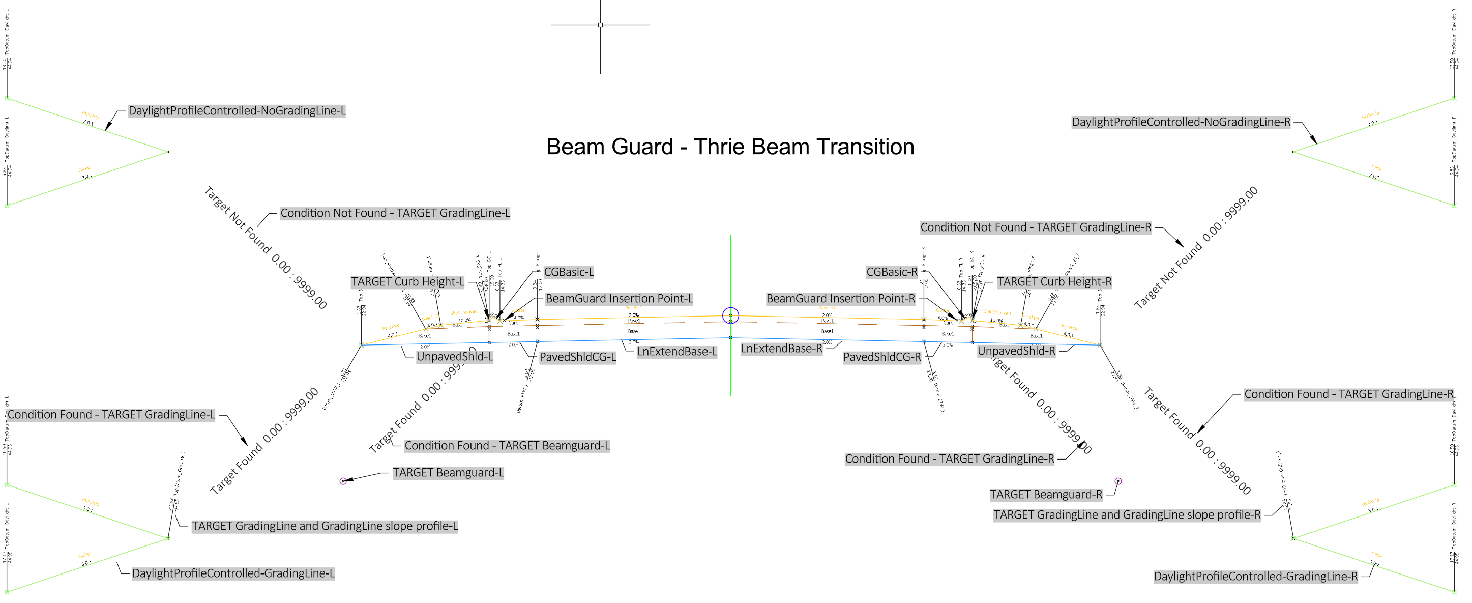
Beam Guard - Thrie Beam Transition
Description
This assembly may be used to model a straight run of beam guard or an energy absorbing terminal (EAT) region with associated lane earthwork. It is intended for the area where thrie beam transition curb is installed with the beam guard. Refer to page 2 of SDD 14B45 for the layout of the curb and SDD 14B44 for more information on MGS energy absorbing terminals.
The assembly is built to accommodate both left and right side construction. If only one side is desired, the subassemblies may be deleted from the other side. The descriptions in the document are for one side of the assembly. The information is mirrored for the opposite side. This is an example assembly that will likely require modifications to fit specific project needs. Common modifications include:
- Changes to the pavement structure
- Selection of the desired side to model
- Integral paved shoulder vs separate paved shoulder
-
Changes to the daylight subassembly to match project conditions
Construction
There are also two conditionals on each side
-
One looks for beam guard alignment targets. If one is found, a generic beam guard block is placed in the section
-
One looks for a GRADELINE alignment targets (see SDD)
-
if none are found, DaylightProfileControlled – Version 26.0 is inserted
-
if one is found, a GRADELINE slope LinkProfileControlled – Version 26.0 is inserted (typically steeper than allowable within clear zone), then DaylightProfileControlled – Version 26.0
-
Warning: Using a GRADELINE slope is not required and often has little impact on the location of the slope intercept of proposed EAT earthwork. It is provided in the assembly to give all options for the design standard detail. Design and construction of EAT earthwork is simpler if it is not used. Engineering judgment needs to applied to appropriate use.
-
Baseline
-
Right
-
LnExtendBase-R
-
PavedShldCG-R this models the base under the curb and gutter
-
CGBasic-R
-
BeamGuard Insertion Point-R
-
Condition Found - TARGET Beamguard-R
-
TARGET Beamguard-R
-
-
TARGET Curb Height-R
-
UnpavedShld-R
-
Condition Not Found - TARGET GradingLine-R
-
DaylightProfileControlled-NoGradingLine-R
-
-
Condition Found - TARGET GradingLine-R
-
TARGET GradingLine and GradingLine slope profile-R
-
DaylightProfileControlled-GradingLine-R
-
-
-
Left
-
LnExtendBase-L
-
PavedShldCG-L this models the base under the curb and gutter
-
CGBasic-L
-
BeamGuard Insertion Point-L
-
Condition Found - TARGET Beamguard-L
-
TARGET Beamguard-L
-
-
TARGET Curb Height-L
-
UnpavedShld-L
-
Condition Not Found - TARGET GradingLine-L
-
DaylightProfileControlled-NoGradingLine-L
-
-
Condition Found - TARGET GradingLine-L
-
TARGET GradingLine and GradingLine slope profile-L
-
DaylightProfileControlled-GradingLine-L
-
-
Beam Guard - Rehab - Thrie Beam Transition
Description
This assembly may be used to model a straight run of beam guard or an energy absorbing terminal (EAT) region where there is only earthwork on the shoulders. It is intended for the area where thrie beam transition curb is installed with the beam guard. Refer to page 2 of SDD 14B45 for the layout of the curb and SDD 14B44 for more information on MGS energy absorbing terminals.
The assembly is built to accommodate both left and right side construction. If only one side is desired, the subassemblies may be deleted from the other side. The descriptions in the document are for one side of the assembly. The information is mirrored for the opposite side. This is an example assembly that will likely require modifications to fit specific project needs. Common modifications include:
- Changes to the pavement structure
- Selection of the desired side to model
- Integral paved shoulder vs separate paved shoulder
-
Changes to the daylight subassembly to match project conditions
Construction
There are also two conditionals on each side
-
One looks for beam guard alignment targets. If one is found, a generic beam guard block is placed in the section
-
One looks for a GRADELINE alignment targets (see SDD)
-
if none are found, DaylightProfileControlled – Version 26.0 is inserted
-
if one is found, a GRADELINE slope LinkProfileControlled – Version 26.0 is inserted (typically steeper than allowable within clear zone), then DaylightProfileControlled – Version 26.0
-
Warning: Using a GRADELINE slope is not required and often has little impact on the location of the slope intercept of proposed EAT earthwork. It is provided in the assembly to give all options for the design standard detail. Design and construction of EAT earthwork is simpler if it is not used. Engineering judgment needs to applied to appropriate use.
-
-
Baseline
-
Right
-
LinkOffsetOnSurface-R
-
LinkWidthAndSlope-R
-
PavedShldCG-R this models the base under the curb and gutter
-
CGBasic-R
-
BeamGuard Insertion Point-R
-
Condition Found - TARGET Beamguard-R
-
TARGET Beamguard-R
-
-
TARGET Curb Height-R
-
UnpavedShld-R
-
Condition Not Found - TARGET GradingLine-R
-
DaylightProfileControlled-NoGradingLine-R
-
-
Condition Found - TARGET GradingLine-R
-
TARGET GradingLine and GradingLine slope profile-R
-
DaylightProfileControlled-GradingLine-R
-
-
-
Left
-
LinkOffsetOnSurface-L
-
LinkWidthAndSlope-L
-
PavedShldCG-L this models the base under the curb and gutter
-
CGBasic-L
-
BeamGuard Insertion Point-L
-
Condition Found - TARGET Beamguard-L
-
TARGET Beamguard-L
-
-
TARGET Curb Height-L
-
UnpavedShld-L
-
Condition Not Found - TARGET GradingLine-L
-
DaylightProfileControlled-NoGradingLine-L
-
-
Condition Found - TARGET GradingLine-L
-
TARGET GradingLine and GradingLine slope profile-L
-
DaylightProfileControlled-GradingLine-L
-
-
-