ShldGeneric - Version: 26.2
Last updated: 2026-06-02
Previous versions still in production can be found below current version
shldr-gnric-01.mp4 10:17
 Description
Behavior
Shoulder width
The shoulder is inserted using widths and thickness parameters provided. If the Unpaved width target offset is inside of the Paved width target, the Unpaved width is set to zero.
There are two options for targeting the paved and unpaved shoulder widths.
- The first option is to use a horizontal target.
- The second option is to use a profile target, where the profile elevations are interpreted as width values.
When both a horizontal and profile target is established, the profile target supersedes the horizontal target.
Pavement depth of adjacent lane
The Adjacent lane pavement thickness can either be manually entered to match the roadway pavement thickness (typically the Pave1 thickness in the LnExtendBase subassembly) or parameter referenced to match that value as well. The Adjacent lane pavement thickness cannot be less than the Pavement thickness parameter which defines the thickness of the paved shoulder. If the Adjacent lane pavement thickness input is less than the Pavement thickness input, the value will be set equal to the Pavement thickness. All base course thicknesses are measured vertically downward from the layer above. The ShldGeneric subassembly Base thickness is determined by whichever value is greater between the Adjacent lane pavement thickness and the Pavement thickness.
Methods of determining paved and unpaved shoulder slopes
Lane and shoulder superelevation rates and transitions associated with the alignment can be used to calculate the paved and/or unpaved shoulder slopes.
When Paved shoulder superelevation method and/or Unpaved shoulder superelevation method are set to User defined, the slopes of the paved and unpaved portion of the shoulder are controlled by the inputs for the Paved shoulder slope and/or Unpaved shoulder slope parameters, unless a parameter reference is set for those two values. If a parameter reference is set for Paved shoulder slope and/or Unpaved shoulder slope, then the adjacent lane's pavement slope (read in by parameter reference) is used to override the user defined values.
Rollover consideration
When Paved shoulder superelevation method is set to User defined, the Paved shoulder slope value can be overridden by Rollover considerations. If the algebraic difference between Paved shoulder slope value and the "calculated adjacent lane slope" exceeds the Max rollover rate then the Paved shoulder slope value will be overridden and paved shoulder slope is calculated so that the algebraic difference between paved shoulder slope value and "calculated adjacent lane slope" equals the Max rollover rate. The Adjacent lane slope method input parameter is used to set a User defined value or the superelevation of the lane next to the paved shoulder. When Paved shoulder superelevation method is set to User defined, the Adjacent lane slope is forced to follow the Paved shoulder slope value unless the Adjacent lane slope method input parameter is set to a User defined value.
Example #1 rollover exceeded scenario:
- Paved shoulder superelevation method = User defined
- Unpaved shoulder superelevation method = Match paved shoulder
- Baseline Outside Lane SE = 5.0%
- Paved shoulder slope = -4.0%
- Adjacent lane slope method = Use outside lane SE
- Max rollover rate = 7.0%
In example #1, the Paved shoulder slope value is overridden by Rollover considerations because the algebraic difference between Paved shoulder slope value and "calculated adjacent lane slope" exceeds the Max rollover rate; (5% -(-4%)) = 9%; 9% > 7%. A new paved shoulder slope will be calculated by the subassembly to be (Calculated Adjacent Lane Slope) – (Max rollover rate) = 5% - 7% = -2%. The unpaved shoulder slope will also = -2% because it was set to match the paved shoulder slope.
When Unpaved shoulder superelevation method is set to User defined, the Unpaved shoulder slope can be overridden by Rollover considerations. After paved shoulder slope value is determined, if the algebraic difference between the Paved shoulder slope and Unpaved shoulder slope value exceeds the Max rollover rate then the Unpaved shoulder slope value will be overridden and Unpaved shoulder slope value is calculated so that the algebraic difference between Paved shoulder slope value and Unpaved shoulder slope equals the Max rollover rate.
Example #2 rollover exceeded scenario (integral shoulder pavement):
- Paved shoulder superelevation method = Outside Lane SE
- Unpaved Shoulder superelevation method = User defined
- Baseline Outside Lane SE = 6.0%
- Unpaved shoulder slope = -4.0%
-
Max rollover rate = 7.0%
In example #2, the Unpaved shoulder slope value is overridden by Rollover considerations because the algebraic difference between Unpaved shoulder slope value and the Paved shoulder slope value exceeds the Max rollover rate. (6% -(-4%)) = 10%; 10% > 7%. A new Unpaved shoulder slope will be calculated by the subassembly to be (Paved shoulder slope) – (Max rollover rate) = 6% - 7% = -1%.
When User defined is not used in the Paved shoulder superelevation method and/or Unpaved shoulder superelevation method, the following logic is followed for calculating the slope of the paved and unpaved portions of the shoulder:
- When Paved shoulder superelevation method and/or Unpaved shoulder superelevation method are set to the baseline superelevation categories, the slopes of the paved and Unpaved portion of the shoulder are controlled by the shoulder SE rates defined for the baseline alignment. If no shoulder SE rates are defined for the baseline alignment, slopes values are defined by the Paved shoulder slope and Unpaved shoulder slope inputs.
- When Match Paved Shoulder is used for Unpaved shoulder superelevation method, the slope of the Unpaved portion of shoulder will always be set equal to the Paved shoulder slope (as determined by Paved shoulder superelevation method and accompanying logic).
Subgrade (datum) slope
The slope of the subgrade (datum) is controlled by the Subgrade superelevation method parameter. When the Subgrade superelevation method is set to User defined, the slope is obtained from input parameter Subgrade slope. The Subgrade slope value can be entered directly or controlled using a parameter reference that sets the slope equal to the subgrade slope of an adjacent lane. Set the Subgrade superelevation method parameter to Match unpaved slope if the entire pavement structure of the unpaved shoulder is to follow rollover criteria.
Base1 and Base2 layer slopes
The slope of all base layer surfaces are controlled by the Base superelevation method. When the Base superelevation method is set to User defined, the slope is obtained from input parameter Base slope. The Base slope value can be entered directly or controlled using a parameter reference that sets the slope equal to the base slope of an adjacent lane. When Match subgrade is used for the Base superelevation method, the slope of the base portion of shoulder will always be set equal to the Subgrade (datum) slope (as determined by Subgrade superelevation method and accompanying logic).
Shoulder foreslopes
The shoulder foreslope is obtained using the Shoulder foreslope and Method to set subgrade improvement foreslope parameters. The Method to set subgrade improvement foreslope parameter is only active when a subgrade improvement layer is present.
The Method to set subgrade improvement foreslope may be set to User defined or set to Follow shoulder foreslope. The Follow shoulder foreslope option sets the subgrade improvement foreslope equal to the shoulder foreslope.
If a value of 0 is used for the Shoulder foreslope, a near vertical link is drawn from the edge of shoulder down to the subgrade (datum) layer. The subgrade improvement foreslope options are then deactivated.
Subgrade improvement
The Subgrade improvement surface is drawn at a width defined by Subgrade improvement width measured from the origin of the subassembly. If this parameter is set to 0 ft., the distance used will be equal to the Paved width + Unpaved width parameters (edge of shoulder).
There are two options for targeting the subgrade improvement width:
- The first option is to use a horizontal target.
- The second option is to use a profile target, where the profile elevations are interpreted as width values.
When both a horizontal and profile target are established, the profile target supersedes the horizontal target.
To close the bottom of the subgrade improvement surface, the Subgrade improvement closure link slope is used to define the slope of the link that extends upward to the intersection with the subgrade (datum surface). If a value of 0 is used for the Subgrade improvement close link slope, a near vertical link will be drawn from the subgrade improvement layer to the subgrade.
When Daylight subgrade improvement to foreslope is Yes, then the subgrade improvement foreslope is drawn, extending from the subgrade shoulder point at a slope defined by the Method to set subgrade improvement foreslope (and accompanying logic) to the bottom of the subgrade improvement. This input also supersedes the Subgrade improvement width and Subgrade improvement closure link slope.
Note:
When Daylight subgrade improvement to foreslope is Yes, the point to attach a subsequent subassembly is now the SGImp intersection point. If a subassembly is attached prior to setting the Daylight subgrade improvement to foreslope to Yes, then the attached subassembly will need to be moved manually.
Unpaved shoulder grade for adjacent curb options
The subassembly can be configured to grade around an adjacent curb subassembly. This option can be used when developing designs where a curb connects with this shoulder subassembly.
To enable the shoulder to conform to an adjacent curb subassembly:
- The Curb and gutter width parameter must have a value greater than 0 (zero)
-
The value must be greater than the Paved width value.
A Curb height, Gutter width, and a Gutter slope parameter is provided to use to obtain these values from the adjacent curb subassembly through the use or a parameter reference for each value. The points, links and shape of the paved shoulder material are removed where the curb subassembly is attached to the assembly.
The unpaved shoulder Base thickness above the Base1 layer is defined by the Adjacent lane pavement thickness value and the unpaved shoulder slope is defined by the Unpaved shoulder slope value or superelevation method used. The unpaved link establishes a slope from the point where the paved shoulder edge would be but begins the link on the back side of where the curb is designated by the Curb width value. To force the unpaved shoulder thickness to follow the top back of curb as the thickness and not follow the standard unpaved shoulder geometry set the Set unpaved shoulder thickness to curb height value to Yes.
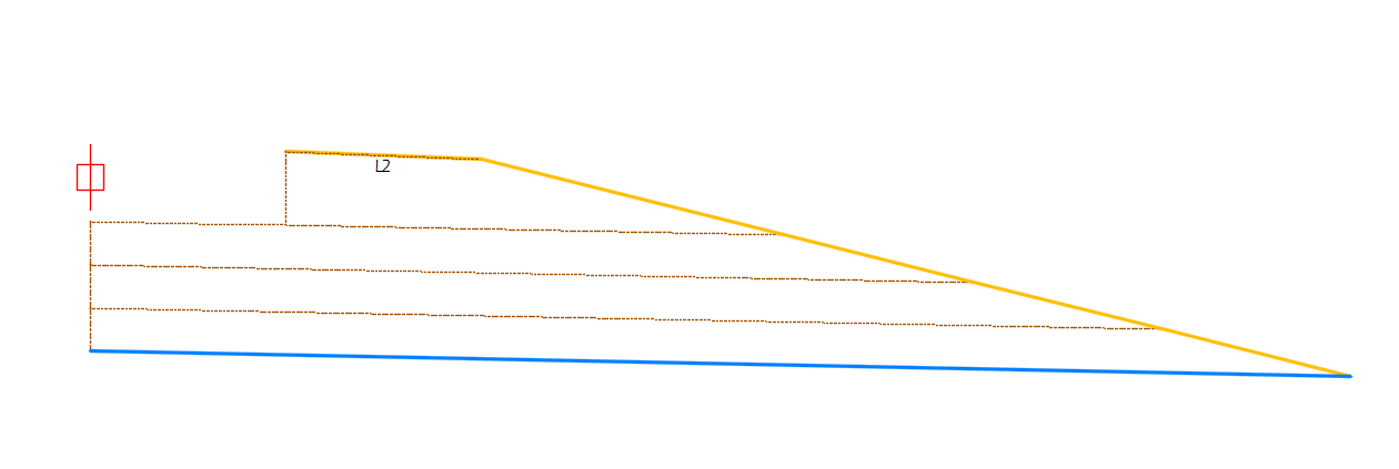
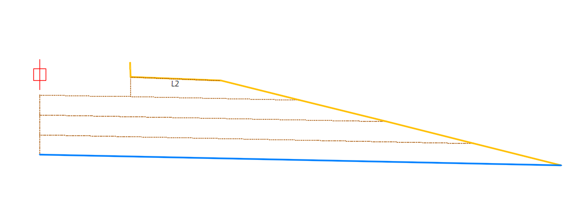
Widening option
The subassembly can be use in rehabilitation scenarios, where the base layers or subgrade (datum) layer is widened outside the existing roadway surface. To enable the widening option, set the Shoulder type parameter to "PartialShoulder". The subassembly will function the same, but now it will include points at the intersection of each base layer and the target surface. The point can then be used as the beginning location of each base surface layer in the widening area.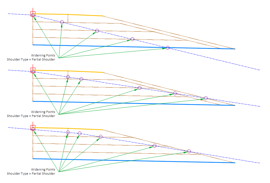
Attachment & layout mode operation
The attachment point is at the inside edge of the paved shoulder, which is typically at the outside edge of the traveled way.
In layout mode, this subassembly displays the links comprising the shoulder for a normal crown roadway situation, using User defined slopes for all layers. This allows the user to preview various scenarios using the User defined slope options.
Input parameters
Info: All dimensions are in feet unless otherwise noted. All slopes are in run-over-rise form (for example 4:1) unless indicated as a percent slope with a "%" sign.
| Parameter | Description | Type | Default |
|---|---|---|---|
| Side | Specifies which side to place the subassembly. | Left/Right | Right |
| Shoulder type | When set to “Partial Shoulder” a point is created at each pave, base and subbase layers where it intersects with the target surface. These points becomes the surface points for a shoulder widening. | List of Options:
| Full Shoulder |
| Paved width | Width of the paved portion of the shoulder. | Numeric, Positive | 3.0' |
| Unpaved width | Unpaved width of the shoulder from the paved shoulder to the shoulder hinge point. | Numeric, Positive | 3.0' |
| Paved thickness | Thickness of the paved shoulder. | Numeric, Positive | 4.50Ad |
| Adjacent lane pavement thickness | Thickness of the pavement on the lane adjacent to shoulder. This thickness defines the depth to the top of the unpaved shoulder layer. This value may be defined from a parameter reference of the adjacent lane pavement thickness. | Numeric, Positive, non-zero | 4.50" |
| Base1 thickness | Thickness of Base1 layer | Numeric, Positive | 12.00" |
| Base2 thickness | Thickness of Base2 layer | Numeric, Positive | 0.0" |
| Subbase thickness | Thickness of Subbase layer | Numeric, Positive | 0.0" |
| Subgrade improvement thickness | Thickness of subgrade improvement layer | Numeric, Positive | 0.0" |
| Max rollover rate | Value is used to limit the maximum algebraic difference between the slope of the Paved or Unpaved Shoulder surfaces and the slope of the adjacent travel lane, also is used to limit the algebraic difference between the slope of the Paved Shoulder and Unpaved Shoulder surfaces. Rollover based shoulder rotation in superelevated sections is described in the Behavior section. | Slope | 8.00% |
| Paved shoulder superelevation method | Specifies whether the top surface of the paved shoulder should use superelevation rates defined for the baseline alignment if it exists, or a User defined Value. | List of options:
| Use outside lane SE |
| Paved shoulder slope | Cross slope of the paved shoulder surface. This value is used in if Paved shoulder superelevation method is set to User defined, or if superelevation is not defined for the baseline alignment. | Slope | -2.0% |
| Unpaved shoulder superelevation method | Specifies whether the top surface of the unpaved shoulder should use SE rates defined for the baseline alignment if it exists, or a User defined value. If Match paved shoulder is used, all other considerations are ignored and the slope of the Unpaved top surface of the shoulder will equal the slope of the Paved portion as determined by Paved shoulder superelevation method. | List of options:
| Use outside shoulder SE |
| Unpaved shoulder slope | Cross slope of the Unpaved shoulder surface. This value is used in if Unpaved shoulder superelevation method is set to User defined, or if superelevation is not defined for the baseline alignment. | Slope | -4.0% |
| Adjacent lane slope method | Specifies the method to use to determine the slope of the adjacent lane. When using Outside or Inside Lane SE of the insertion side, or the opposite side SE multiplied by -1.0, the SE rate that is used is that which is defined for the baseline. User defined slope will automatically be used when no baseline SE is defined. This parameter controls the slope of link "L4" which is the extension of the bottom of adjacent pavement or the extension of the bottom of adjacent paved should | List of options:
| Use outside lane SE |
| Adjacent lane slope | Slope value to be used when calculating rollover and Adjacent lane slope method set to User defined. Value can (and should) be set by a parameter reference. | Slope | -2.0% |
| Base superelevation method | When multiple base layers exist, entry determines how the base layers are sloped. | List of options:
| Match subgrade |
| Base slope | Slope value to be used when Base superelevation method is set to User defined. Value can (and should) be set by a parameter reference. | Slope | -2.0% |
| Subgrade superelevation method | Specifies the method used to determine the slope of the subgrade (datum) surface. Use the opposite side SE x -1, results in the subgrade surface slope being equal to Superelevation Slope defined for the baseline on the side opposite the insertion side, multiplied by -1.0. If Match Paved Shoulder or Match Unpaved Shoulder is selected, the Subgrade will be parallel to the top of shoulder surface as determined by Paved shoulder superelevation method or Unpaved shoulder superelevation method. Selecting User defined applies the slope specified the or the Subgrade slope input parameter | List of options:
| Use Outside Lane SE |
| Subgrade slope | Fixed cross slope of the subgrade (datum) surface. This value is used if User defined is selected as the Subgrade superelevation method or superelevation is not specified for the baseline alignment. | Slope | -2.0% |
| Shoulder foreslope | Slope of the Foreslope of the shoulder which extends from the Shoulder Hinge Point to the Subgrade Shoulder Point. | Slope, Positive | 4:1 |
| Use 3 inches or 3/4 inch aggregate on shoulder foreslope | Determines whether the optional 3" of ¾" aggregate is placed on the foreslope of the shoulder, from the bottom of the ¾" base layer adjacent to the paved shoulder to the subgrade shoulder point as shown in WisDOT FDM 14-5-10. Option only available when more than one base layer is used. | Yes/No | No |
| Subgrade improvement width | Width of the subgrade improvement layer measured from the subassembly origin. Entry of zero matches the width of the shoulder. | Numeric, Positive | 0.0' |
| Subgrade improvement closure link slope | Slope of link that extends upward from the end point of the bottom of the subgrade improvement surface to the intersection with the subgrade. | Slope, Positive | 0:1 |
| Daylight subgrade improvement to foreslope | The insertion of the subgrade improvement foreslope link, which is the foreslope link inserted after the Subgrade Shoulder Point, can be avoided by setting this parameter to No. | Yes/No | No |
| Method to set subgrade improvement foreslope | Method to calculate the subgrade improvement foreslope. If User defined is selected, the foreslope is determined by the Subgrade improvement foreslope input parameter. If Slope from target profile elevation is selected, the elevation of a targeted profile is interpreted as a slope. If the target profile is not valid, the Subgrade improvement foreslope input parameter value is used. If Follow shoulder foreslope is selected, the Subgrade improvement foreslope will always match the shoulder foreslope. | List of options:
| Follow shoulder foreslope |
| Subgrade improvement foreslope | Slope of the Subgrade improvement foreslope of the shoulder which extends from the Subgrade Shoulder Point to projected subgrade improvement layer. | Slope, Positive | 4:1 |
| Curb and gutter width (parameter reference) | The width value is required to be larger than the paved shoulder width. A width of zero or a value less than the value of the paved shoulder width keeps all curb shoulder function Off. | Numeric, Positive | 0.0 |
| Curb height (parameter reference) | This value is obtained from the curb height output of an attached curb subassembly through a parameter reference. | Numeric, Positive | 0.0 |
| Curb width (parameter reference) | This value is obtained from the curb width output of an attached curb subassembly through a parameter reference. | Numeric, Positive | 2.0 |
| Gutter slope (parameter reference) | This value is obtained from the gutter slope output of an attached curb subassembly through a parameter reference. | Slope | -4.0% |
| Set unpaved shoulder thickness to curb height | A Yes value matches the unpaved shoulder thickness to the Curb height value, otherwise the unpaved shoulder thickness follows the paved shoulder thickness. | Yes/No | No |
| Right point suffix | List of options to use for adding a suffix to all point codes on the right side. The user defined option uses the value of the “Right user defined point suffix” parameter. | String, Combo List of Options:
| _R |
| Left point suffix | List of options to use for adding a suffix to all point codes on the right side. The user defined option uses the value of the “Right user defined point suffix” parameter. | String, Combo List of Options:
| _L |
| Right user defined point suffix | User defined right point code suffix | String | |
| Left user defined point suffix | User defined left point code suffix | String |
Target parameters
This section lists the parameters in this subassembly that can be mapped to a target object such as a surface, alignment, or profile object in a drawing. For more information, see Setting and Editing Targets in the AutoCAD Civil 3D User's Guide Help.
| Parameter | Description | Status |
|---|---|---|
| Surface for widening | Surface that is targeted for defining the widening partial shoulder points | Optional |
| Foreslope from profile | May be used to set the shoulder foreslope by interpreting the elevation of an object as a slope. The following object types can be used as targets for specifying this elevation: profiles, 3D polylines, feature lines, or survey figures. | Optional |
| Match to curb switch from profile | May be used to switch the Set unpaved shoulder thickness to curb height option to Yes or No. A value of 0 (zero) sets the option to NO, and a value greater than 0 (zero) sets the option to Yes. | Optional |
| Paved shoulder slope from profile | May be used to set the paved shoulder slope by interpreting the elevation of an object as a slope. The following object types can be used as targets for specifying this elevation: profiles, 3D polylines, feature lines, or survey figures. | Optional |
| Paved width from profile | May be used to set the paved shoulder width by interpreting the elevation of the object as a width. The following object types can be used as targets for specifying this elevation: profiles, 3D polylines, feature lines, or survey figures. | Optional |
| Paved width | Object that defines the horizontal location of the edge of the paved portion of the shoulder. The following object types can be used as targets for specifying the width: alignments, polylines, feature lines, or survey features. | Optional |
| Subgrade improvement foreslope from profile | May be used to set the subgrade improvement foreslope by interpreting the elevation of an object as a slope. The following object types can be used as targets for specifying this elevation: profiles, 3D polylines, feature lines, or survey figures. | Optional |
| Subgrade improvement width from profile | May be used to set the subgrade improvement width by interpreting the elevation of the object as a width. The following object types can be used as targets for specifying this elevation: profiles, 3D polylines, feature lines, or survey figures. | Optional |
| Subgrade improvement width | Object that defines the horizontal location of the end of the subgrade improvement. The following object types can be used as targets for specifying the width: alignments, polylines, feature lines, or survey features. | Optional |
| Subgrade slope from profile | May be used to set the subgrade slope by interpreting the elevation of an object as a slope. The following object types can be used as targets for specifying this elevation: profiles, 3D polylines, feature lines, or survey figures. | Optional |
| Unpaved shoulder thickness from profile | May be used to set the unpaved shoulder thickness by interpreting the elevation of an object as a thickness. The following object types can be used as targets for specifying this elevation: profiles, 3D polylines, feature lines, or survey figures. | Optional |
| Unpaved shoulder slope from profile | May be used to set the unpaved shoulder slope by interpreting the elevation of an object as a slope. The following object types can be used as targets for specifying this elevation: profiles, 3D polylines, feature lines, or survey figures. | Optional |
| Unpaved width from profile | May be used to set the unpaved shoulder width by interpreting the elevation of the object as a width. The following object types can be used as targets for specifying this elevation: profiles, 3D polylines, feature lines, or survey figures. | Optional |
| Unpaved width | Object that defines the horizontal location of the shoulder hinge point. The following object types can be used as targets for specifying the width: alignments, polylines, feature lines, or survey features. | Optional |
Output parameters
| Parameter | Description | Type |
|---|---|---|
| Absolute value shoulder foreslope [Output] | Slope of the link from the edge of shoulder to the subgrade shoulder point. Expressed as a positive value regardless of slope direction. | Slope |
| Absolute value subgrade improvement foreslope [Output] | Slope of the link from the subgrade shoulder point to the projection of the subgrade improvement layer. Expressed as a positive value regardless of slope direction. | Slope |
| Shoulder foreslope[Output] | Slope of the link from the edge of shoulder to the subgrade shoulder point. Upward slope is positive, downward slope is negative. | Slope |
| Subgrade improvement foreslope [Output] | Slope of the link from the subgrade shoulder point to the projection of the subgrade improvement layer. Upward slope is positive, downward slope is negative. | Slope |
| Shoulder Pave Slope [Output] | Slope of the link from the insertion point to the edge of the paved shoulder. Upward slope is positive, downward slope is negative. | Slope |
| Shoulder Unpaved Slope [Output] | Slope of the link from the edge of the paved shoulder to the edge of shoulder. Upward slope is positive, downward slope is negative. | Slope |
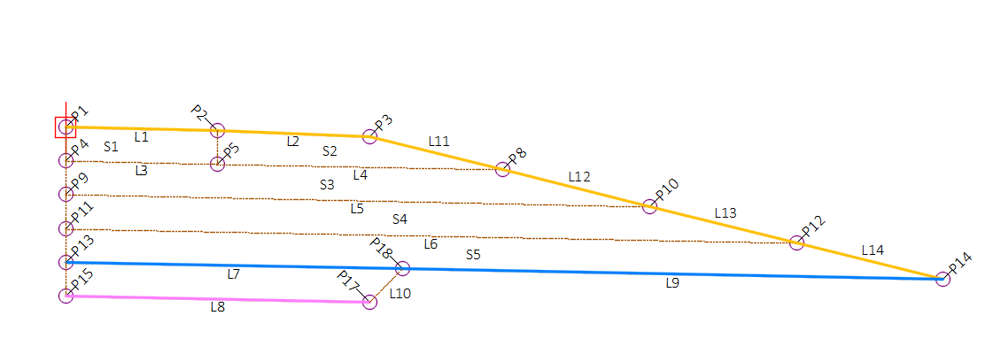
Coding diagram
Use 3 inch aggregate set to Yes
Use 3 inch aggregate set to No
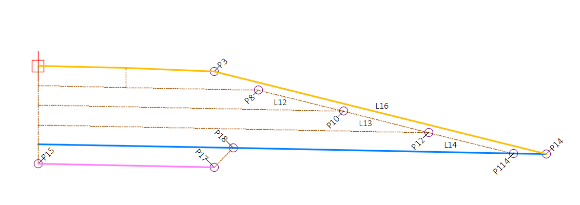
Adjacent lane pavement thickness set as a parameter reference of the adjacent lane Paved thickness value and the adjacent lane paved thickness is greater than the shoulder paved thickness
Point, Link, and Shape codes
| Point/Link/Shape | Codes | Description |
|---|---|---|
| P1 | Top_ETW | Origin (top inside edge of shoulder) |
| P2 | Top_EPS | Edge of paved shoulder, finish grade |
| P3 | Top_EGS | Edge of gravel Shoulder; outer edge of Unpaved portions of shoulder on finished grade |
| P4 | Pave1_ETW[] | Bottom of paved shoulder at inside edge |
| P5 | ShldPave1_EPS[] | Bottom of edge of paved shoulder |
| P6 | Pave1_ETW[] | Bottom of adjacent pavement edge |
| P8 | Top_ShldPave1_ES | Edge of shoulder on Pave1 Layer |
| P9 | Base1_ETW[] | Inside edge of shoulder on bottom of Base1 layer |
| P10 | Base1_ES[] | Edge of shoulder on bottom of Base1 layer |
| P11 | Base2_ETW[] | Inside edge of shoulder on bottom of Base2 layer |
| P12 | Base2_ES[] | Edge of shoulder on bottom of Base2 layer |
| P13 | Datum_ETW | Inside edge of shoulder bottom of subbase layer (datum) |
| P14 | Datum_SGSP, Top_SGSP | Subgrade shoulder point |
| P15 | SGImp_ETW | Inside edge of shoulder bottom of subgrade improvement layer |
| P16 | TopDatum_SGImp | End of subgrade improvement foreslope |
| P17 | SGImp_ES | Outside edge of subgrade improvement layer |
| P18 | SGImp_Daylight | Intersection of subgrade improvement closure link and subgrade (datum) |
| P114 | Datum_ES[] | Bottom of ¾" base on foreslope at subgrade |
| P206 | Pave1_Widen | Intersection of Pave1 layer with target surface |
| P209 | Base1_Widen | Intersection of Base1 layer with target surface |
| P211 | Base2_Widen | Intersection of Base2 layer with target surface |
| P213 | Datum_Sub_Widen | Intersection of Datum layer with target surface |
| P214 | Datum_Widen_Out | Datum shoulder edge |
| P215 | Datum_Widen_In | Datum pave edge |
| P216 | Datum_Widen_ShldAgg | Datum at 3" of 3/4" aggregate on shoulder foreslope |
| L1 | Top,ShldPaved,LABELPCT | Finish grade of the paved shoulder |
| L2 | Top,ShldUnpaved,LABELPCT | Finish grade of unpaved shoulder |
| L3 | ShldPave1 | Bottom of paved shoulder |
| L4 | Pave1 | Bottom of adjacent pavement |
| L5 | Base1 | Bottom of the first base layer |
| L6 | Base2 | Bottom of second base layer |
| L7 | Datum | Bottom of lowest base layer |
| L8 | SGImp | Bottom of subgrade improvement |
| L9 | Datum | Bottom of lowest base layer outside of the subgrade improvement intercept |
| L10 | SGImp | Subgrade improvement closure link |
| L11 | BaseFslp | Foreslope of base layers |
| L11-L14 | Top | Foreslope of base layers |
| L15 | Top,SGImpFslp | Subgrade improvement foreslope link |
| L16 | Top,BaseFslp | Top of ¾" aggregate foreslope |
| L100 | Pave_Edge_In[] | Inside edge of pavement |
| L101 | Pave_Edge_Out[] | Outside edge of pavement |
| L102-L106 | Base_Edge[] | Inside edge of base layers |
| L108 | Datum | Bottom ¾ inch aggregate foreslope at subgrade |
| L109 | Datum | Datum partial shoulder |
| L111 | Top | Back of curb |
| S1 | ShldPave1 | Paved shoulder |
| S2 | Base | Base layer under paved shoulder and adjacent to lane pavement |
| S3 | Base1 | First base layer |
| S4 | Base2 | Second base layer |
| S5 | Subbase | Subbase layer |
| S6 | SGImp | Subgrade improvement layer |
ShldGeneric - Version: 26.0
Description
This subassembly inserts a paved or Unpaved shoulder with all pavement, base, subbase, and subgrade improvement layers per WisDOT FDM 11-5-15. In addition, use 3 inch Aggregate input determines whether the optional 3" of ¾" Aggregate is placed on the foreslope of the shoulder, from the bottom of the ¾" base layer adjacent to the paved shoulder to the subgrade shoulder point as shown in WisDOT FDM 14-5-01. The foreslope may be held constant according the Shoulder foreslope input parameter, or it can vary with a superelevation assignment or slope from profile target.
Behavior
Shoulder width
The shoulder is inserted using widths and thickness parameters provided. If the Unpaved Width target offset is inside of the Paved width target, the Unpaved width is set to zero. There are two options for targeting the paved and unpaved shoulder widths. The first option is to use a horizontal target. The second option is to use a profile target, where the profile elevations are interpreted as width values. When both a horizontal and profile target is established, the profile target supersedes the horizontal target.
Pavement depth of adjacent lane
All base course thicknesses are measured vertically downward above layer. The thickness of the base located above the Pave1 layer (bottom of adjacent lane pavement) is defined by the Adjacent lane pavement thickness input. This thickness cannot be less than the Pavement thickness parameter which defines the thickness of the paved shoulder. If the Adjacent lane pavement thickness input is less than the Pavement thickness input, the value will be set equal to the Pavement thickness.
Methods of determining paved and unpaved shoulder slopes
When a User define slope is used in the Paved shoulder superelevation type and/or Unpaved shoulder superelevation type, the following logic is followed for calculating the slope of the paved and Unpaved portions of the shoulder:
When Paved shoulder superelevation type and/or Unpaved shoulder superelevation type are set to User defined, the slopes of the paved and Unpaved portion of the shoulder are controlled by the inputs for the Paved shoulder slope and/or Unpaved shoulder slope parameters, unless a parameter reference is set for those two values. If a parameter reference is set for Paved shoulder slope and/or Unpaved shoulder slope, then the adjacent lane's pavement slope (read in by parameter reference) is used to override the user defined values.
Rollover consideration
When Paved shoulder superelevation type is set to User defined, the paved shoulder slope value can be overridden by Rollover considerations. If the algebraic difference between Paved shoulder slopevalue and "calculated adjacent lane slope" exceeds theMax rollover rate then the Paved shoulder slopevalue will be overridden and paved shoulder slope is calculated so that the algebraic difference between paved shoulder slope value and "calculated adjacent lane slope" equals the Max rollover rate. Method to obtain slope of adjacent laneinput parameter is used to determine "calculated adjacent lane slope" value. Example #1 rollover exceeded scenario:
- Paved shoulder superelevation type = User defined
- Unpaved shoulder superelevation type = Match paved shoulder
- Paved shoulder slope = -4.0%
- Method to obtain slope of adjacent lane = Use outside lane SE
- Baseline Outside Lane SE = 5.0%
-
Max rollover rate = 7.0%
In example #1 scenario the Paved shoulder slope value is overridden by Rollover considerations because the algebraic difference between Paved shoulder slopevalue and "calculated adjacent lane slope" exceeds theMax rollover rate. (5% -(-4%)) = 9%; 9% > 7%. A new paved shoulder slope will be calculated by the subassembly to be (Calculated Adjacent Lane Slope) – (Max rollover rate) = 5% - 7% = -2%. Unpaved shoulder slope will also = -2% because it must match the paved shoulder slope.
When Unpaved shoulder superelevation type is set to User defined, the Unpaved shoulder slope can be overridden by Rollover considerations. After paved shoulder slope value is determined, if the algebraic difference between paved shoulder slope value and Unpaved shoulder slope exceeds the Max rollover rate then the Unpaved shoulder slope value will be overridden and Unpaved shoulder slope value is calculated so that the algebraic difference between paved shoulder slope value and Unpaved shoulder slope equals the Max rollover rate. Example #2 rollover exceeded scenario (integral shoulder pavement):
- Paved shoulder superelevation type = Outside Lane SE
- Unpaved Shoulder superelevation type = Fixed Slope
- Baseline Outside Lane SE = 6.0%
- Unpaved shoulder slope = -4.0%
-
Max rollover rate = 7.0%
In example #2 scenario the Unpaved shoulder slope value is overridden by Rollover considerations because the algebraic difference between Unpaved shoulder slope value and paved shoulder slope value exceeds the Max rollover rate. (6% -(-4%)) = 10%; 10% > 7%. A new Unpaved shoulder slope will be calculated by the subassembly to be (paved shoulder slope) – (Max rollover rate) = 6% - 7% = -1%.
When User defined is not used in the Paved shoulder superelevation type and/or Unpaved shoulder superelevation type, the following logic is followed for calculating the slope of the paved and unpaved portions of the shoulder:
When Paved shoulder superelevation type and/or Unpaved shoulder superelevation type are set to and of the baseline superelevation categories, the slopes of the paved and Unpaved portion of the shoulder are controlled by the shoulder SE rates defined for the baseline alignment. If no shoulder SE rates are defined for the baseline alignment, slopes values are defined by the Paved shoulder slope and Unpaved shoulder slope inputs.
When Match Paved Shoulder is used for Unpaved shoulder superelevation type, the slope of the Unpaved portion of shoulder will always be set equal to the Paved shoulder slope (as determined by Paved shoulder superelevation type and accompanying logic).
Subgrade (datum) slope
The slope of the subgrade (datum) is controlled by the Subgrade superelevation method parameter. User has the option of entering a user defined slope to be used, following the insertion side superelevation defined for the baseline alignment, following the opposite side superelevation multiplied by -1.0, matching paved shoulder slope as determined by Paved shoulder superelevation type, or matching Unpaved shoulder slope as determined by Unpaved shoulder superelevation type. When Subgrade SE Method is set to User defined, this slope is obtained from input parameter Subgrade slope which can be controlled using a Parameter Reference that sets the slope equal to that of the subgrade surface of an adjacent lane.
Base layer slopes
The slope of all base layer surfaces are controlled by the Base layer slope method. User has the option of entering a user defined slope to be used, following the insertion side superelevation defined for the baseline alignment, following the opposite side superelevation multiplied by -1.0, or matching subgrade slope (as determined by Subgrade superelevation method and accompanying logic).
Shoulder foreslopes
The shoulder foreslope is obtained using the Method to set shoulder foreslope and Method to set subgrade improvement foreslope parameters. The Method to set subgrade improvement foreslope parameter is only active when a subgrade improvement layer is present. For both parameters, there are the following options available:
- User defined: Typically used for constant slope applications. This sets the foreslope to the value given for the Shoulder foreslope input parameter.
- Slope from target profile elevation: Typically used for variable slope applications. This sets the foreslope according to the elevation of a targeted profile. The profile elevation is interpreted as a slope value.
-
Inside lane SE, Outside lane SE, Inside shoulder SE, Outside shoulder SE: Typically used for variable slope applications. This sets the foreslope according to the baseline superelevation category assigned. If the baseline does not have superelevation assigned to the chosen category, the Shoulder foreslope parameter is used.
The Method to set subgrade improvement foreslope has the additional Follow shoulder foreslope option. This option sets the subgrade improvement foreslope equal to the shoulder foreslope.
If a value of 0 is used for the Shoulder foreslope, a near vertical link is drawn from the edge of shoulder down to the subgrade (datum) layer. The subgrade improvement foreslope options are then deactivated.
Subgrade improvement
The Subgrade improvement surface is drawn at a width defined by Subgrade improvement width measured from the origin of the subassembly. If this parameter is set to 0 ft., the distance used will be equal to the Paved width + Unpaved width parameters (edge of shoulder). There are two options for targeting the subgrade improvement width. The first option is to use a horizontal target. The second option is to use a profile target, where the profile elevations are interpreted as width values. When both a horizontal and profile target are established, the profile target supersedes the horizontal target. To close the bottom of the subgrade improvement surface, the Subgrade improvement closure link slope is used to define the slope of the link that extends upward to the intersection with the subgrade (datum surface). If a value of 0 is used for the Subgrade improvement close link slope, a near vertical link will be drawn from the subgrade improvement layer to the subgrade.
When Show subgrade improvement foreslope is yes, then the subgrade improvement foreslope is drawn, extending from the subgrade shoulder point at a slope defined by the Method to set subgrade improvement foreslope (and accompanying logic) to the intersection with a temporary projection of the bottom of the subgrade improvement.
Widening option
The subassembly can be use in rehabilitation scenarios, where the base layers or subgrade (datum) layer is widened outside the existing roadway surface. To enable the widening option, set the Include surface widening pointsparameter to "PartialShoulder". The subassembly will function the same, but now it will include points at the intersection of each base layer and the target surface. The point can then be used as the beginning location of each base surface layer in the widening area.
Attachment & layout mode operation
The attachment point is at the inside edge of the paved shoulder, which is typically at the outside edge of the traveled way.
In layout mode, this subassembly displays the links comprising the shoulder for a normal crown roadway situation, using User defined slopes for all layers. This allows the user to preview various scenarios using the User defined slope options.
Input parameters
Info: All dimensions are in feet unless otherwise noted. All slopes are in run-over-rise form (for example 4:1) unless indicated as a percent slope with a "%" sign.
| Parameter | Description | Type | Default |
|---|---|---|---|
| Side | Specifies which side to place the subassembly. | Left/Right | Right |
| Shoulder type | When set to “PartialShoulder” a point is created at the intersection of each base layer and the target surface. This point becomes the beginning surface point for a shoulder widening. | String, Combo List of Options: FullShoulder PartialShoulder |
FullShoulder |
| Paved width | Width of the paved portion of the Shoulder. | Numeric, Positive | 3.0' |
| Unpaved width | Unpaved width of the shoulder from the paved shoulder to the shoulder hinge point. | Numeric, Positive | 3.0' |
| Pavement thickness | Thickness of the paved shoulder. | Numeric, Positive | 0.375' |
| Adjacent lane pavement thickness | Thickness of the pavement on the lane adjacent to shoulder. This thickness defines the depth to the top of the Base1 layer. | Numeric, Positive, non-zero | 0.375' |
| Base1 thickness | Thickness of Base1 layer | Numeric, Positive | 1.0' |
| Base2 thickness | Thickness of Base2 layer | Numeric, Positive | 0.0' |
| Subbase thickness | Thickness of Subbase layer | Numeric, Positive | 0.0' |
| Subgrade improvement thickness | Thickness of subgrade improvement layer | Numeric, Positive | 0.0' |
| Subgrade improvement width | Width of the subgrade improvement layer measured from the subassembly origin. Entry of zero matches the width of the shoulder. | Numeric, Positive | 0.0' |
| Subgrade improvement closure link slope | Slope of link that extends upward from the end point of the bottom of the subgrade improvement surface to the intersection with the subgrade. | Slope, Positive | 0:1 |
| Use 3 inch aggregate | Use 3 inch Aggregate input determines whether the optional 3" of ¾" Aggregate is placed on the foreslope of the shoulder, from the bottom of the ¾" base layer adjacent to the paved shoulder to the subgrade shoulder point as shown in WisDOT FDM 14-5-01 | Yes/No | No |
| Paved shoulder superelevation type | Specifies whether the top surface of the paved shoulder should use superelevation rates defined for the baseline alignment if it exists, or a User defined Value. |
List of options:
|
Use outside lane SE |
| Unpaved shoulder superelevation type | Specifies whether the top surface of the unpaved shoulder should use SE rates defined for the baseline alignment if it exists, or a User defined value. If Match paved shoulder is used, all other considerations are ignored and the slope of the UnPaved top surface of the shoulder will equal the slope of the Paved portion as determined by Paved shoulder superelevation type. |
List of options:
|
Match paved shoulder |
| Paved shoulder slope | Cross slope of the paved shoulder surface. This value is used in if Paved shoulder superelevation type is set to User defined, or if superelevation is not defined for the baseline alignment. | Slope | -2.0% |
| Unpaved shoulder slope | Cross slope of the Unpaved shoulder surface. This value is used in if Unpaved shoulder superelevation type is set to User defined, or if superelevation is not defined for the baseline alignment. | Slope | -4.0% |
| Method to set shoulder foreslope | Method to calculate the shoulder foreslope. If User defined is selected, the foreslope is determined by the Shoulder foreslope input parameter. If Slope from target profile elevation is selected, the elevation of a targeted profile is interpreted as a slope. If the target profile is not valid, the Shoulder foreslope input parameter value is used. If any of the superelevation options are chosen, the baseline superelevation is used to set the shoulder foreslope. If superelevation is not set for the baseline, the Shoulder foreslope input parameter is used. |
List of options:
|
User defined |
| Shoulder foreslope | Slope of the Foreslope of the shoulder which extends from the Shoulder Hinge Point to the Subgrade Shoulder Point. | Slope, Positive | 4:1 |
| Show subgrade improvement foreslope | The insertion of the subgrade improvement foreslope link, which is the foreslope link inserted after the Subgrade Shoulder Point, can be avoided by setting this parameter to No. | Yes/No | Yes |
| Method to set subgrade improvement foreslope | Method to calculate the subgrade improvement foreslope. If User defined is selected, the foreslope is determined by the Subgrade improvement foreslope input parameter. If Slope from target profile elevation is selected, the elevation of a targeted profile is interpreted as a slope. If the target profile is not valid, the Subgrade improvement foreslope input parameter value is used. If any of the superelevation options are chosen, the baseline superelevation is used to set the shoulder foreslope. If superelevation is not set for the baseline, the Shoulder foreslope input parameter is used. If Follow shoulder foreslope is selected, the Subgrade improvement foreslope will always match the shoulder foreslope. |
List of options:
|
Follow shoulder foreslope |
| Subgrade improvement foreslope | Slope of the Subgrade improvement foreslope of the shoulder which extends from the Subgrade Shoulder Point to projected subgrade improvement layer. | Slope, Positive | 4:1 |
| Subgrade superelevation method | Specifies the method used to determine the slope of the subgrade (datum) surface. Use the opposite side SE x -1, results in the subgrade surface slope being equal to Superelevation Slope defined for the baseline on the side opposite the insertion side, multiplied by -1.0. If Match Paved Shoulder or Match Unpaved Shoulder is selected, the Subgrade will be parallel to the top of shoulder surface as determined by Paved shoulder superelevation type or Unpaved shoulder superelevation type. Selecting User defined applies the slope specified the or the Subgrade slope input parameter |
List of options:
|
Use Outside Lane SE |
| Subgrade slope | Fixed cross slope of the subgrade (datum) surface. This value is used if User defined is selected as the Subgrade superelevation type or superelevation is not specified for the baseline alignment. | Slope | -2% |
| Base layer slope method | When multiple base layers exist, entry determines how the base layers are sloped. |
List of options:
|
Match subgrade |
| Base layer slope | Slope value to be used when Base layer slope method is set to User defined. Value can (and should) be set by a parameter reference. | Slope | -2% |
| Max rollover rate | Value is used to limit the maximum algebraic difference between the slope of the Paved or Unpaved Shoulder surfaces and the slope of the adjacent travel lane, also is used to limit the algebraic difference between the slope of the Paved Shoulder and Unpaved Shoulder surfaces. Rollover based shoulder rotation in superelevated sections is described in the Behavior section. | Slope | 7% |
| Method to obtain slope of adjacent lane | Specifies the method to use to determine the slope of the adjacent lane.When using Outside or Inside Lane SE of the insertion side, or the opposite side SE multiplied by -1.0, the SE rate that is used is that which is defined for the baseline. User defined slope will automatically be used when no baseline SE is defined. This parameter controls the slope of link "L4" which is the extension of the bottom of adjacent pavement or the extension of the bottom of adjacent paved shoulder. |
List of options:
|
Use outside lane SE |
| Slope of adjacent lane | Slope value to be used when calculating rollover and Method to Obtain Slope of Adjacent Lane is set to User defined. Value can (and should) be set by a parameter reference. | Slope | -2% |
| Right point suffix | List of options to use for adding a suffix to all point codes on the right side. The user defined option uses the value of the “Right user defined point suffix” parameter. |
String, Combo _NW_R _NE_R _SW_R _SE_R _MED_R NoSuffix PointCodeNumber |
_R |
| Left point suffix | List of options to use for adding a suffix to all point codes on the right side. The user defined option uses the value of the “Right user defined point suffix” parameter. |
String, Combo _NW_L _NE_L _SW_L _SE_L _MED_L NoSuffix PointCodeNumber |
_L |
| Right user defined point suffix | User defined right point code suffix | String | |
| Left user defined point suffix | User defined left point code suffix | String |
Target parameters
This section lists the parameters in this subassembly that can be mapped to a target object such as a surface, alignment, or profile object in a drawing. For more information, see Setting and Editing Targets in the AutoCAD Civil 3D User's Guide Help.
| Parameter | Description | Status |
|---|---|---|
| Surface for widening | Surface that is targeted for defining the widening partial shoulder points | Optional |
| Paved width | Object that defines the horizontal location of the edge of the paved portion of the shoulder. The following object types can be used as targets for specifying the width:alignments, polylines, feature lines, or survey features. | Optional |
| Unpaved width | Object that defines the horizontal location of the shoulder hinge point. The following object types can be used as targets for specifying the width:alignments, polylines, feature lines, or survey features. | Optional |
| Subgrade improvement width | Object that defines the horizontal location of the end of the subgrade improvement. The following object types can be used as targets for specifying the width:alignments, polylines, feature lines, or survey features. | Optional |
| Paved shoulder slope from profile | May be used to set the paved shoulder slope by interpreting the elevation of an object as a slope. The following object types can be used as targets for specifying this elevation:profiles, 3D polylines, feature lines, or survey figures. | Optional |
| Unpaved shoulder slope from profile | May be used to set the unpaved shoulder slope by interpreting the elevation of an object as a slope. The following object types can be used as targets for specifying this elevation:profiles, 3D polylines, feature lines, or survey figures. | Optional |
| Subgrade slope from profile | May be used to set the subgrade slope by interpreting the elevation of an object as a slope. The following object types can be used as targets for specifying this elevation:profiles, 3D polylines, feature lines, or survey figures. | Optional |
| Foreslope from profile | May be used to set the shoulder foreslope by interpreting the elevation of an object as a slope.The following object types can be used as targets for specifying this elevation:profiles, 3D polylines, feature lines, or survey figures. | Optional |
| Subgrade improvement foreslope from profile | May be used to set the subgrade improvement foreslope by interpreting the elevation of an object as a slope.The following object types can be used as targets for specifying this elevation:profiles, 3D polylines, feature lines, or survey figures. | Optional |
| Paved width from profile | May be used to set the paved shoulder width by interpreting the elevation of the object as a width. The following object types can be used as targets for specifying this elevation:profiles, 3D polylines, feature lines, or survey figures. | Optional |
| Unpaved width from profile | May be used to set the unpaved shoulder width by interpreting the elevation of the object as a width. The following object types can be used as targets for specifying this elevation:profiles, 3D polylines, feature lines, or survey figures. | Optional |
| Subgrade improvement width from profile | May be used to set the subgrade improvement width by interpreting the elevation of the object as a width. The following object types can be used as targets for specifying this elevation:profiles, 3D polylines, feature lines, or survey figures. | Optional |
Output parameters
| Parameter | Description | Type |
|---|---|---|
| Shoulder foreslope[Output] | Slope of the link from the edge of shoulder to the subgrade shoulder point. Upward slope is positive, downward slope is negative. | Slope |
| Absolute value shoulder foreslope | Slope of the link from the edge of shoulder to the subgrade shoulder point. Expressed as a positive value regardless of slope direction. | Slope |
| Subgrade improvement foreslope [Output] | Slope of the link from the subgrade shoulder point to the projection of the subgrade improvement layer. Upward slope is positive, downward slope is negative. | Slope |
| Absolute value subgrade improvement foreslope [Output] | Slope of the link from the subgrade shoulder point to the projection of the subgrade improvement layer. Expressed as a positive value regardless of slope direction. | Slope |
Coding diagram
Use 3 inch aggregate set to Yes
Use 3 inch aggregate set to No
Point, Link, and Shape codes
| Point/Link/Shape | Codes | Description |
|---|---|---|
| P1 | Top_ETW | Origin (top inside edge of shoulder) |
| P2 | Top_EPS | Edge of paved shoulder, finish grade |
| P3 | Top_EGS | Edge of gravel Shoulder; outer edge of Unpaved portions of shoulder on finished grade |
| P4 | Pave1_ETW+ | Bottom of paved shoulder at inside edge |
| P5 | ShldPave1_EPS | Bottom of edge of paved shoulder |
| P6 | Pave1_ETW+ | Bottom of adjacent pavement edge |
| P8 | ShldPave1_ES+ | Edge of shoulder on Pave1 Layer |
| P9 | Base1_ETW+ | Inside edge of shoulder on bottom of Base1 layer |
| P10 | Base1_ES | Edge of shoulder on bottom of Base1 layer |
| P11 | Base2_ETW | Inside edge of shoulder on bottom of Base2 layer |
| P12 | Base2_ES | Edge of shoulder on bottom of Base2 layer |
| P13 | Datum_ETW | Inside edge of shoulder bottom of subbase layer (datum) |
| P14 | Datum_SGSP, Top_SGSP | Subgrade shoulder point |
| P15 | SGImp_ETW | Inside edge of shoulder bottom of subgrade improvement layer |
| P16 | TopDatum_SGImp | End of subgrade improvement foreslope |
| P17 | SGImp_ES | Outside edge of subgrade improvement layer |
| P18 | SGImp_Daylight | Intersection of subgrade improvement closure link and subgrade (datum) |
| P114 | Datum_ES | Bottom of ¾" base on foreslope at subgrade |
| P206 | Pave1_Widen | Intersection of Pave1 layer with target surface |
| P209 | Base1_Widen | Intersection of Base1 layer with target surface |
| P211 | Base2_Widen | Intersection of Base2 layer with target surface |
| P213 | Subbase_Widen | Intersection of Datum layer with target surface |
| P214 | Datum_Widen_Out | Datum 3" aggregate widen |
| P215 | Datum_Widen_In | Datum pave edge |
| L1 | Top,ShldPaved | Finish grade of the paved shoulder |
| L2 | Top,ShldUnpaved | Finish grade of unpaved shoulder |
| L3 | ShldPave1 | Bottom of paved shoulder |
| L4 | Pave1 | Bottom of adjacent pavement |
| L5 | Base1 | Bottom of the first base layer |
| L6 | Base2 | Bottom of second base layer |
| L7 | Datum | Bottom of lowest base layer |
| L8 | SGImp | Bottom of subgrade improvement |
| L9 | Datum | Bottom of lowest base layer outside of the subgrade improvement intercept |
| L10 | SGImp | Subgrade improvement closure link |
| L11-L14 | Top,BaseFslp | Foreslope of base layers |
| L15 | Top,SGImpFslp | Subgrade improvement foreslope link |
| L16 | Top,BaseFslp | Top of ¾" aggregate foreslope |
| L100 | Pave_Edge_In | Inside edge of pavement |
| L101 | Pave_Edge_Out | Outside edge of pavement |
| L102-L106 | Base_Edge | Inside edge of base layers |
| L108 | Datum | Bottom ¾ inch aggregate foreslope at subgrade |
| S1 | ShldPave1 | Paved shoulder |
| S2 | Base | Base layer under paved shoulder and adjacent to lane pavement |
| S3 | Base1 | First base layer |
| S4 | Base2 | Second base layer |
| S5 | Subbase | Subbase layer |
| S6 | SGImp | Subgrade improvement layer |