Points - Point Station Offset to UDP
Last updated: 2026-01-06
Overview
This utility populates point user-defined property (UDP) fields with alignment information for station and offset. One or two alignments can be used as references. Selected points with these UDPs can then be used in conjunction with WisDOT table styles to display this information. This utility can also create new point groups by selecting points from an existing point group or picking points from model space.
Tip: This method of label and table creation for points is recommended for situations where multiple alignments need to be referenced for station/offset. If that functionality is not needed, Dynamic station/offset labels and tables on a surface with pipe networks provides live updates to label and table data.
Warning: If changes occur to the alignments or points after the utility is run, the utility will have to be run again to update any tables that are using the UDP data.
Usage
WisDOT Design tab > Design panel > Points dropdown > Point Station Offset to UDP
The tool can also be accessed from the command line: POINTSOUDP.
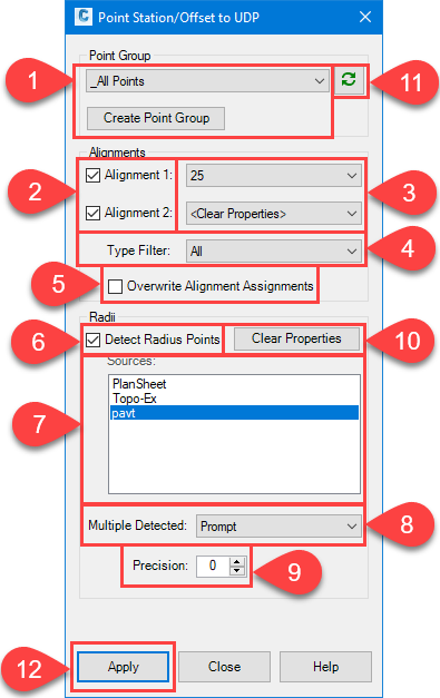
- Choose a Point Group to apply UDP values to from the list. If a Point Group containing the desired Points has not been created, click the Create Point Group button to build a new Point Group.
- Check the boxes to select which Alignment UDP fields should be populated. When unchecked, Points that already have an Alignment assigned to the Alignment1 and/or Alignment 2 properties, will still have the corresponding station/offset and alignment description files updated.
- Use the menus to select the alignments to use for calculating the stations/offsets to the points. To clear the UDP fields, select Clear Properties
- An alignment type filter is provided to narrow the list of alignments shown in the menus.
- Check the Overwrite Alignment Assignment box to overwrite any previously established Alignment assignments for the points.
- This tool will attempt to populate the Radius UDP field by searching for all Polyline, Feature Line, Alignment, and Arc objects and comparing the center points of all arc subcomponents with the cogo point coordinates. Check this box to perform this operation.
- This lists the active drawing, and all XReference names. Select one or multiple to search for matching arc center points.
-
Select the method to use when multiple arc center points are detected.
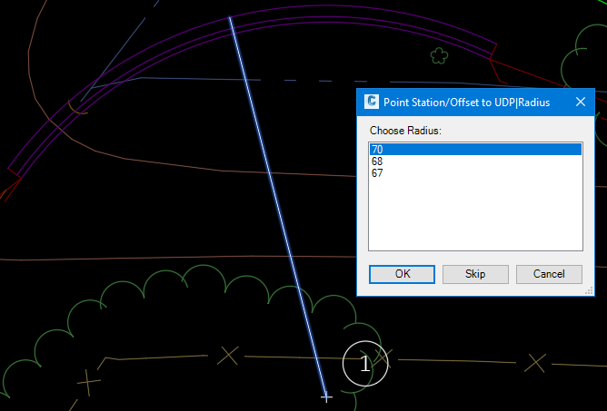
- Prompt: Prompt to choose which arc radius should be uses. When multiple possible arcs are found, a new dialog is presented to choose the desired radius value. The cogo point, arc, and a temporary graphic depicting the radius is shown. Select the desired radius and click OK. To skip assigning a Radius value to the point, click Skip. To cancel applying radius values, click Cancel. This will cancel the process of applying radius values for all points.
- Use Smallest: The smallest detected radius value will be used.
- Use Largest: The largest detected radius value will be used.
- Select the precision of the Radius value up to 3 decimal places. The value indicates the number of decimal places.
- Clears the Radius property for all points in the selected Point Group.
- Refreshes the dialog with the latest drawing data.
- Apply to populate the UDP fields for the selected Point Group.
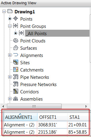
Verifying the Results
Once the utility is run, the point properties can be verified by clicking on the point group in the Toolspace > Prospector > Point Groups and looking at the point properties in the preview window of the Prospector.