Traffic control crossovers: corridor-based
Last updated: 2016-05-16
Exercise files: crdr-ele-trfc-cntrl-crssovr-data-C3D16.zip
Exercise files: crdr-ele-trfc-cntrl-crssovr-finished-data-C3D16.zip
 Crossover design with Civil 3D
There are multiple ways to design a crossover with Civil 3D and every situation is different. This document discusses one method for modeling crossovers using a combination of tools in Civil 3D. First, here are some best practices and design recommendations to help with the crossover geometry.
- Make sure the crossover placement allows for adequate room in the construction zone.
- Place the crossover in a location that is visible to approaching motorists.
- Look at the longitudinal profile of your roadway and try to place the crossover in a location where the pavement will drain. If the area is flat, consider using Slotted Corrugated Metal Pipe Surface Drains. Good drainage may sometimes be achieved by warping the pavement slopes.
- Use SDD 15D11 as a guide. Design for no less than 10 mph below posted speed.
- Use the existing roadway crown to your advantage when selecting curve radii.
- The crossover model will be dependent on the existing median pavement edges. It is critical to survey these pavement edges at a minimum. Ideally, the entire median (pavement edge to pavement edge) should be surveyed.
Here is one method to model a median crossover with Civil 3D. The naming shown is based on a East-West roadway. To avoid rework, finalize the location of the crossover prior to constructing the surface models.
Create crossover geometry
- Create a new drawing with the WisDOT template and give it an appropriate name such as Crdr-Crossover.dwg. Data shortcut reference the following:
- NB and SB reference line alignments
- NB and SB centerline alignments
- Existing Surface (ideally with a supplemental median survey included)
- Xreference the project mapping.
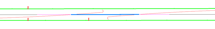
- Determine the best location for the crossover. Create the horizontal geometry for the median crossover using alignments. All the edgeline alignments can be created, but only the edge of shoulder alignments will be used for this modeling process. Show the gore areas with the alignments.
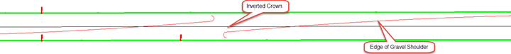
- Create an alignment representing the inverted crown of the crossover. Typically this is located down the center of the median. The alignment should extent well past the anticipated location where it would intersection the crossover subgrade shoulder points.
- Create and existing surface profile for the EB and WB reference line alignments.
Create crossover setup surfaces and surface profiles
- Insert the Crossover Setup assembly from the WisDOT assemblies palette. Adjust the lane parameters to match the required pavement structure.
- Create a corridor called Setup-Crossover
- Set the corridor begin and end stations to just beyond the crossover extents.
- Use the EB alignment, Existing Surface profile, and the assembly from step 1.
- Recommended frequency is 2.5 ft.
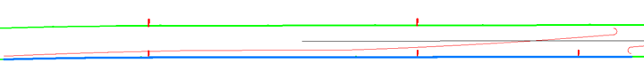
- Target the first lane to the inverted crown alignment
- Target the second lane to the WB reference line alignment and existing surface profile.
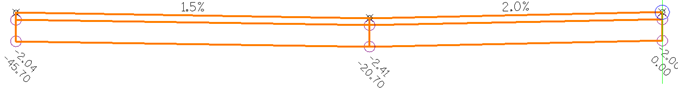
- Review the lane cross-slopes in the corridor section editor. The right lane slope will be constant and the other will vary to match the terrain. Check to make sure the variable slopes are reasonable. You may need to adjust the location of the inverted crown line or modify the slope of the constant slope lane in the assembly. Superelevation or Profile Slope Control tools can be used to vary the lane slopes to aid in pavement drainage or to better match the existing conditions.
- In the Surfaces tab of the corridor properties, create the Crdr-Setup-Crossover-Top, Crdr-Setup-Crossover-Base, and a Crdr-Setup-Crossover-Datum surfaces. If there are other layers in the pavement structure, create those surfaces too.
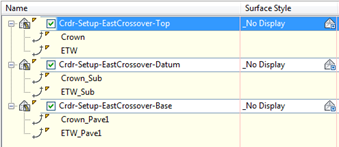
- Set the corridor code set style to No Display.
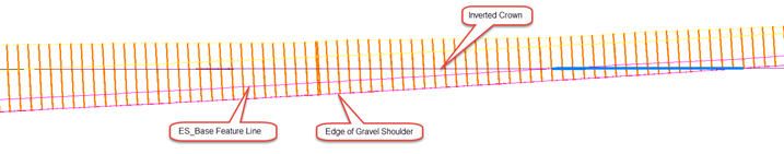
- Create surface profiles on the Crdr-Setup-Crossover-Top surface for the inverted crown and edge of gravel shoulder alignments.
Create Proposed Corridor
- Insert the following assemblies from the WisDOT assemblies palette.
- Top-Base-Datum FLs
- Base-Datum FLs
- Datum FL
- Gore FLs with Left Slope
- Gore FLs with Right Slope
- Create a new corridor proposed work corridor named appropriately.
- Add the Inverted Crown alignment and surface profile as the baseline.
- Use the Top-Base-Datum FLs assembly to create a region that extends from crossover edge of gravel shoulder to edge of shoulder gravel shoulder.
- Add the EB reference line and existing surface profile as a baseline.
- Using the Top-Base-Datum FLs assembly, add a region to the EB baseline that extends the limits of work along the EB reference line.
- Repeat steps 5 and 6 for the WB reference line.
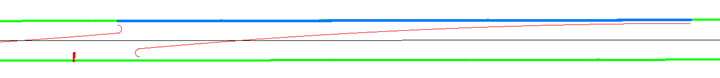
- Add one of the crossover edge of shoulder alignments and surface profile to the corridor as a baseline.
- Add a region using either the Gore FLs with Left Slope or Gore FLs with Right Slope assembly. (Choose based on the direction of the alignment, and direction of the daylight slope)
- The region limits should extend from the end of the crossover limits to the start of the gore radius.
- Target the Existing surface using the SlopeToDaylight subassembly
- Target the Crdr-Setup-Crossover-Datum surface using the SlopeToDaylight_Sub subassembly
- Target the Crdr-Setup-Crossover-Base surface using the SlopeToES_Base subassembly
- Add a second region using the Top-Base-Datum FLs assembly that extends through the gore radius.
- Repeat Steps 8-10 for the other edge of gravel shoulder alignment/surface profile.
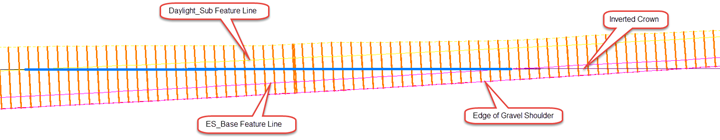
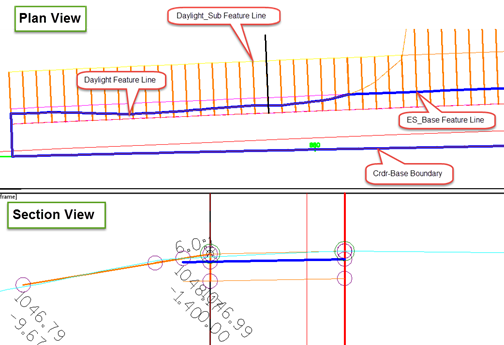
- Add a region to the Inverted Crown baseline that extends from the edge of gravel shoulder to the point where the inverted crown alignment intersects the ES_Base feature line created in step 9.
- Add a region to the Inverted Crown baseline that extends from the point where the inverted crown alignment intersects the ES_Base feature line to the point where it intersects the Daylight_Sub feature line
- Repeat steps 12 and 13 for the opposite side of the crossover.
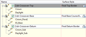
- Create corridor surfaces for Top, Base, and Datum. Required feature lines are shown below.
Create Corridor Top Surface Boundary
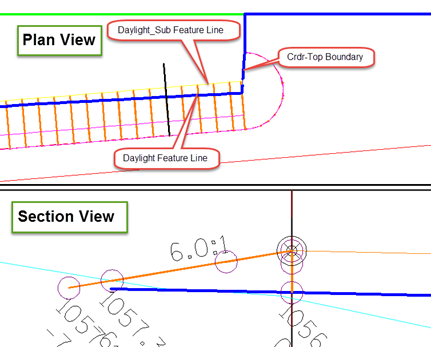
- For the Top surface, create a corridor surface boundary using the interactive method. The boundary should follow the Daylight feature line along the shoulder baselines and follow the Crown feature line along the EB/WB reference lines.
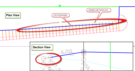
- You will likely notice areas where the boundary falls inside of the Daylight_Sub feature line. This is normal and typically occurs at the ends of the crossover limits and near the gores. These are areas where the shoulder foreslope matches into the existing ground before reaching the Daylight_Sub feature line.
Create Corridor Datum Surface Boundary
- For the Datum surface, create a corridor surface boundary using the interactive method. The boundary should follow either the Daylight or Daylight_Sub feature lines along the shoulder baselines (whichever is most interior to the crossover at any given point). Along the EB and WB baselines, the boundary should follow the Crown_Sub feature line.
- The boundary will likely jump back and forth between the Daylight and Daylight_Sub feature lines. Just like the corridor top surface boundary, this is normal and typically occurs at the ends of the crossover limits and near the gores. These are areas where the shoulder foreslope matches into the existing ground before reaching the Daylight_Sub feature line.
Alternative Boundary Creation Method
Corridor surface boundary creation is a key element to this workflow. If you are not accustomed to using the interactive boundary creation method in conjunction with editing an interactive boundary after it has been create, the task can be challenging. An alternative to using the interactive method is to create a polyline boundary. This can be done by extracting the required feature lines from the corridor. Explode the feature lines so you are left with 3D polylines. Then, using the trim, extend, and join commands, a closed polyline can be created and used for the boundary.
Create Corridor Base Surface Boundary
- For the Base surface, create a corridor surface boundary using the interactive method. The boundary should follow either the Daylight or ES_Base feature lines along the shoulder baselines (whichever is most interior to the crossover at any given point). Along the EB and WB baselines, the boundary should follow the Crown_Pave1 feature line.
- The boundary will likely jump back and forth between the Daylight and ES_Base feature lines. Just like the corridor top and datum surface boundaries, this is normal and typically occurs at the ends of the crossover limits and near the gores. These are areas where the shoulder foreslope matches into the existing ground before reaching the ES_Base feature line.
Create Refinement Surfaces
- Data reference each corridor surface into its respective refinement surface drawing.
- Refinement-Top
- Paste in Crdr-Top
- Refinement-Base
- Paste in Crdr-Base
- Refinement-Datum
- Paste in Refinement-Top
- Paste in Crdr-Datum
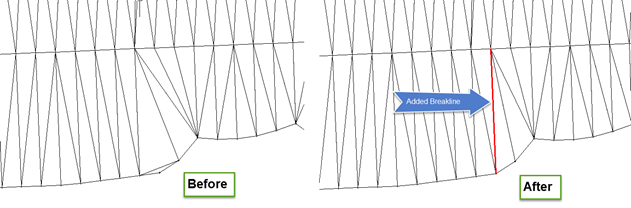
- Surface refinements for the three surface type is similar. For each surface, add a breakline at the gores as shown below.
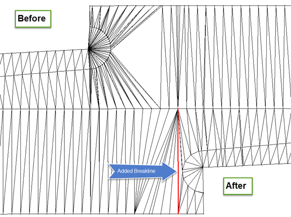
- For the Refinement-Top surface, check the slope areas for locations like this. Add breaklines as needed.