Traffic control crossovers: feature line-based
Last updated: 2015-04-21
 Modeling crossovers
There are multiple ways to design a crossover with Civil 3D and every situation is different. This document discusses one method for modeling crossovers using a combination of tools in Civil 3D. First, here are some best practices and design recommendations to help with the crossover geometry.
Make sure the crossover placement allows for adequate room in the construction zone.
Place the crossover in a location that is visible to approaching motorists.
Look at the longitudinal profile of your roadway and try to place the crossover in a location where the pavement will drain. If the area is flat, consider using Slotted Corrugated Metal Pipe Surface Drains. Good drainage may sometimes be achieved by warping the pavement slopes.
Use SDD 15D11 as a guide. Design for no less than 10 mph below posted speed.
Use the existing roadway crown to your advantage when selecting curve radii.
The crossover model will be dependent on the existing median pavement edges. It is a best practice to survey these pavement edges at a minimum. Ideally, the entire median (pavement edge to pavement edge) should be surveyed.
Here is one method to model a median crossover with Civil 3D. The naming shown is based on a North-South roadway. To avoid rework, finalize the location of the crossover prior to constructing the surface models.
Crossover geometry
- Create a new drawing with the WisDOT template and give it an appropriate name such as Crossover Edgelines.dwg. Data shortcut reference the following:
- NB and SB reference line alignments and existing surface profiles
- NB and SB centerline alignments
- Existing Surface (ideally with a supplemental median survey included)
- Xreference the project mapping.
- Determine the best location for the crossover. Draw the horizontal geometry for the median crossover. Be sure to include the edge of pavement and edge of shoulder line work for the gore areas. This can be done with lines and arcs, the end result needs to be continuous polylines. Use the proper layers. Save and close the drawing
Crossover setup surfaces
- Create a new drawing with the WisDOT template and give it an appropriate name such as Crossover Setup Corridor.dwg. Data shortcut the following:
- NB and SB reference line alignments and existing surface profiles
- Existing Surface (ideally with a supplemental median survey included)
- Create a joint polyline that represents the inverted crown location of the crossover median. The polyline should extend through the limits of the crossover.

- Create an assembly consisting of two lanes.
- Create a corridor called Crossover Setup.
- Set the corridor begin and end stations to the crossover extents.
- Use the NB alignment, Existing Surface profile, and the assembly from step 6.
- Recommended frequency is 5 ft.
- Target the first lane to the inverted crown polyline
- Target the second lane to the SB reference line alignment and existing surface profile.
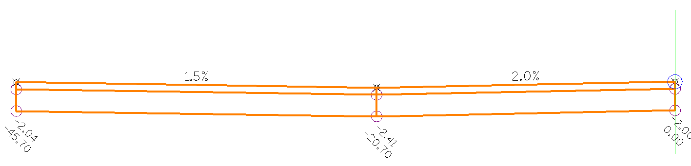
- Review the lane cross-slopes in the corridor section editor. The right lane slope will be constant and the other will vary to match the terrain. Check to make sure the variable slopes are reasonable. You may need to adjust the location of the inverted crown line or modify the slope of the constant slope lane in the assembly. Also, superelevation can be established on the NB alignment to vary the right lane slope to aid in pavement drainage or to better match the existing conditions.
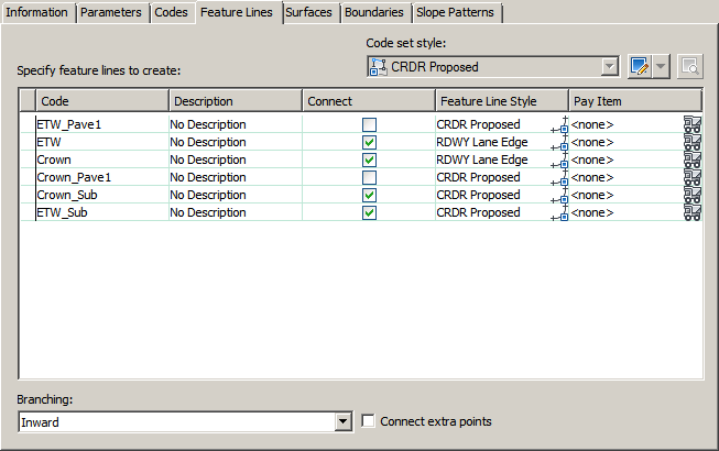
- Turn off all unnecessary feature lines in the corridor properties Feature Lines tab. The feature lines that are needed are ETW, Crown, ETW_Sub, and Crown_Sub.
- In the Surfaces tab of the corridor properties, create a Top and a Datum surface.
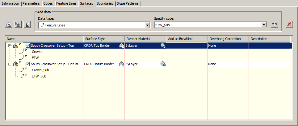
- Save the drawing and create data shortcuts for the Top and Datum surfaces.
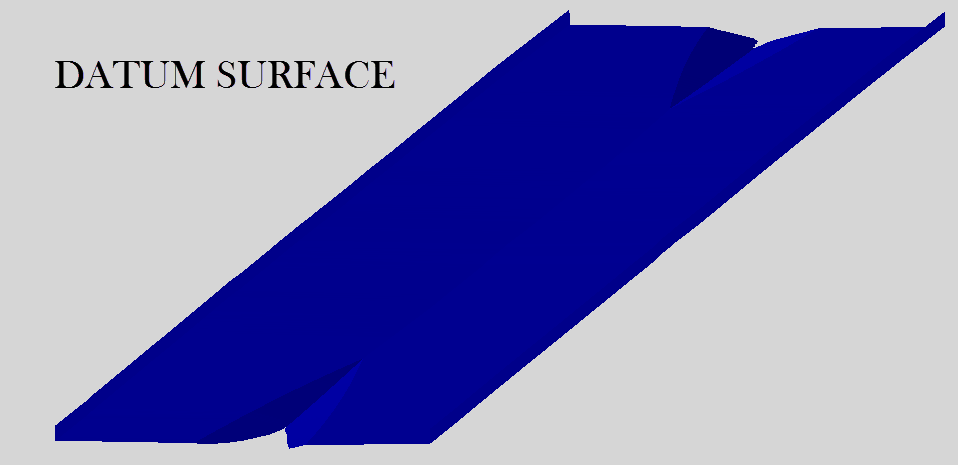
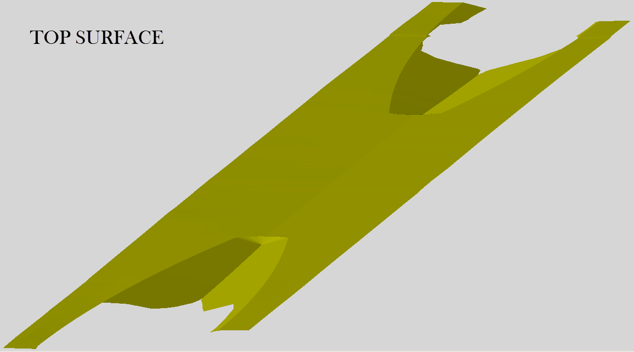
Crossover top surface
- Create a new drawing with the WisDOT template and give it an appropriate name such as Crossover Top Surface.dwg. Data shortcut the following:
- Crossover Setup - Top surface
- Exist surface
- Xreference the Crossover Edgelines.dwg file.
- Create a new Site called "Crossover - Top".
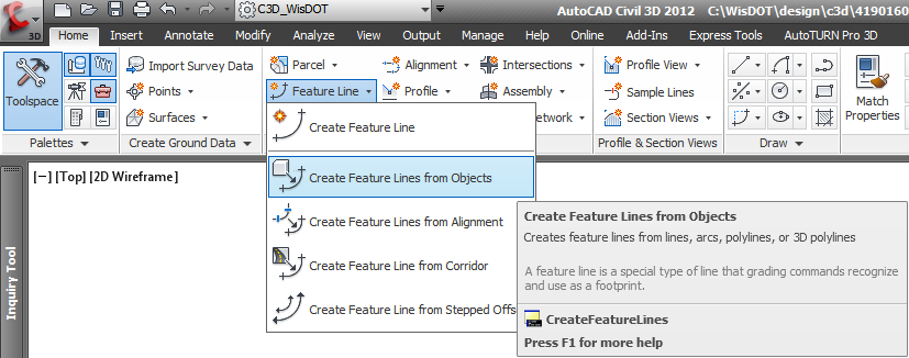
- Create feature lines for the cross over edge lines using the Create Feature Line from Objects command. Place these feature lines in the Crossover - Top Site. Do not assign a style. Place the feature lines on the appropriate layers. Assign elevations from the Crossover Setup - Top surface. Accept the default weeding factors.
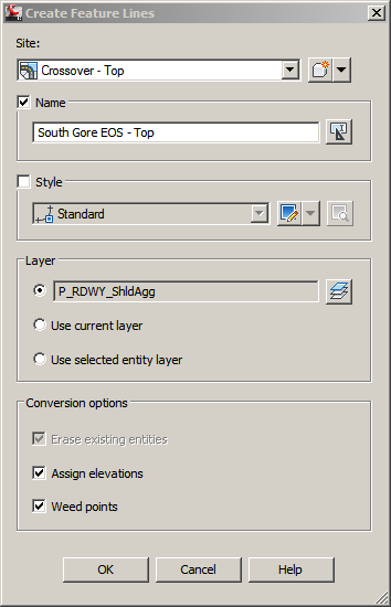
Example naming convention: (EOP = Edge of Pavement, EOS - Edge of Shoulder)
South Gore EOP - Top
South Gore EOS - Top
North Gore EOP - Top
North Gore EOS - Top
- Create feature lines representing the NB and SB edges of pavement and place them in the Crossover - Top site. Give them appropriate names like NB EOP - Top and SB EOP - Top. Assign elevations from the Crossover Setup - Top surface.
- Create a feature line representing the inverted crown location between the edge of shoulder gore radii and place it in the Crossover - Top site. Give it an appropriate name like Inverted Crown - Top. Assign elevations from the Crossover Setup - Top surface.
- Create a feature line at each end of the crossover limits connecting closing off the work area. Name them something appropriate like NB North EOP, NB South EOP, SB South EOP, SB North EOP.
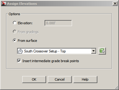
- From the Modify tab, select the Elevations from Surface command from the Edit Elevations panel. Choose the Crossover Setup - Top surface and check Insert intermediate grade break points. Select all of the feature lines.
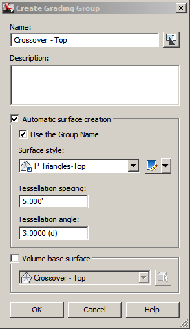
- In the Crossover - Top site, create a grading group called Crossover - Top. Turn on Automatic Surface Creation. Check Use the Group Name, give it a style of P Triangles-Top, and set the Tessellation spacing to 5'
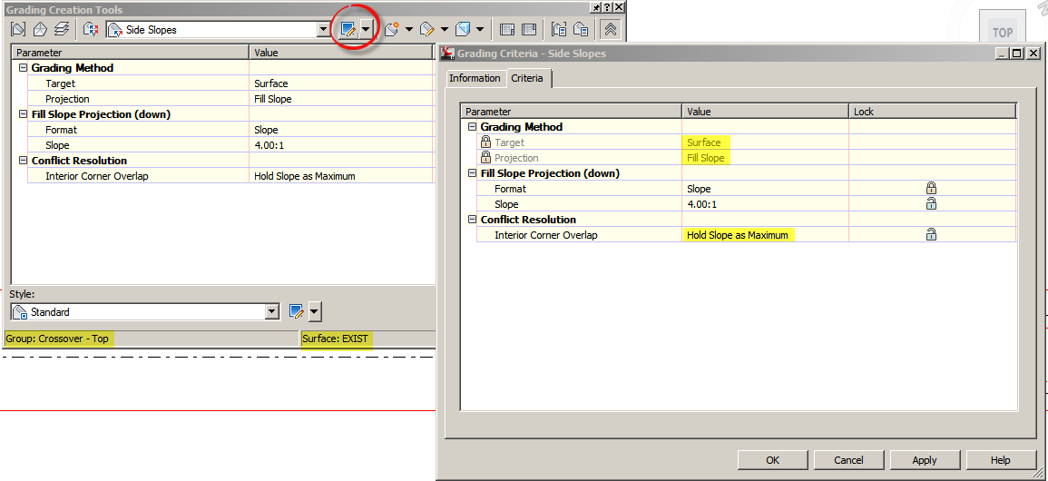
- Open the Grading Creation tools dialogue. Edit the Grading Criteria to match your project conditions. Make sure Target is set to Surface and Interior Corner Overlap is set to Hold Slope as Maximum.
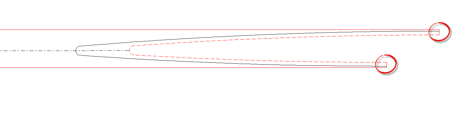
- Create Gradings off of the Gore EOS - Top feature lines. Set your target surface to Exist. Apply to the entire length.
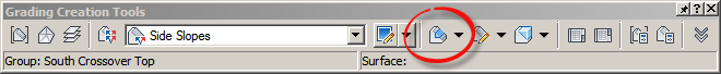
- From the Grading Creation Toolbar, select the Create Grading Infill command. Select each of the areas of the crossover to complete the surface creation. These areas include four shoulder areas and two pavement areas.
- The Crossover Top surface should now be complete. Inspect the surface for abnormalities and make any surface edits as needed.
- Save the drawing and create a data shortcut for the Crossover - Top surface.
Crossover datum surface
- Create a copy of the Crossover Top Surface.dwg file and rename it as Crossover Datum Surface.dwg
- Open the Crossover Datum Surface.dwg file.
- Right click on the Crossover Top Grading Group in the Toolspace - Prospector and select properties. On the Information Tab, uncheck Automatic Surface Creation. Confirm the deletion of the Crossover Top surface.
- Right click on the Crossover Top Grading Group in the Toolspace - Prospector and select Delete. Confirm the deletion of all Gradings.
- Create a new Site called SGSP - Setup
- Select the two Gore EOS feature lines and move them into the SGSP - Setup site.
- Rename the Crossover - Top Site properties, rename the site to Crossover - Datum
- Delete the following feature lines from the Crossover - Datum site:
- South Gore EOP - Top
- North Gore EOP - Top
- NB North End - Top
- NB South End - Top
- SB South End - Top
- SB North End - Top
- Rename the remaining feature lines in the Crossover - Datum site with a Datum designation instead of Top.
- Create a new Grading Group in the SGSP - Setup site called SGSP Setup. Do not turn on Automatic Surface Creation.
- Open the Grading Creation Tools. Set the target surface to Crossover Setup - Datum. Use the same Grading Criteria that was used for the Crossover Top gradings.
- Create gradings on each of the Gore EOS feature lines.
- From the Toolspace - Settings tab, navigate to Gradings - Styles - Standard. Right click on standard and select Edit. On the Display tab, turn off all Plan view component visibility except for Daylight Line.
- Type EXPLODE at the command line. Select the two gradings. What will remain are two 3D polylines representing the crossover subgrade shoulder point.
- Data shortcut reference the Crossover Top surface. Give it a border only style.
- Select the Crossover Top surface and choose the Extract Objects command from the contextual ribbon. Click Ok. Turn the Crossover Top surface to the No Display style.
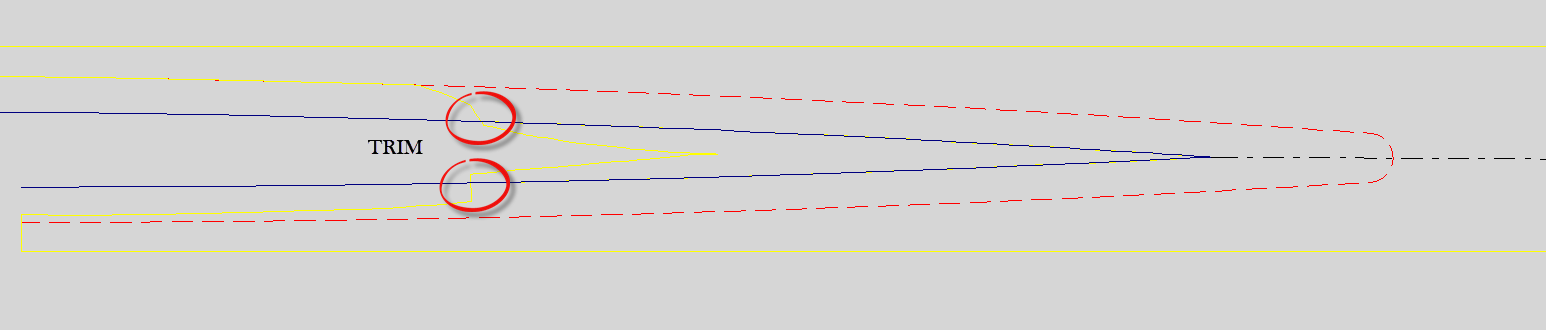
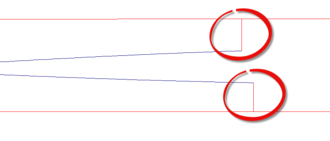
- Using the Trim command, trim the ends of the subgrade shoulder point 3d polyline against the Crossover Top surface boundary 3d polyline. The Crossover Top surface boundary 3d polyline can then be deleted.
- Use the Create Feature Lines from Objects command to convert the SGSP polylines to feature lines. Give them appropriate names like SGSP south and SGSP north. Do not assign a style. Place them on the P_RDWY_Subg_ShldPt layer. Erase existing entities, Assign Elevations from the Crossover Setup Datum surface. Do not weed points. These feature lines belong in the Crossover - Datum site.
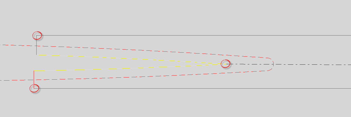
- Create a feature line at each end of the subgrade shoulder point feature lines to a point perpendicular to the NB EOP and SB EOP feature lines. Similar to step 7 in the Create Crossover Top Surface segment.
- Grip edit the NB EOP and SB EOP feature lines ends to match the feature lines created in step 19.
- Grip edit the Inverted Crown feature line to snap to the subgrade shoulder point feature line.
- From the Modify tab, select the Elevations from Surface command from the Edit Elevations panel. Choose the Crossover Setup - Datum surface and check Insert intermediate grade break points. Select all of the feature lines except the Gore EOS - Top feature lines.
- Create a new grading group in the Crossover - Datum site called Crossover - Datum - Infills. Turn on Automatic Surface Creation. Check Use the Group Name, give it a No Display style, and set the Tessellation spacing to 5'.
- Open the Grading Creation Tools. Place infills for the two areas enclosed by the SGSP feature lines, NB & SB EOP feature lines, and Inverted Crown feature line.
- From the Modify tab - Edit Geometry Panel, select the Stepped Offset command. Set the offset distance to 0.01'. Select the NB EOP and SB EOP feature lines. The elevation does not matter yet.
- Rename the feature lines created in step 25 to NB Exist and SB Exist.
- Use the Elevations from Surface command to assign elevations to the NB Exist and SB Exist feature lines from the Exist surface.
- Create a new surface called Crossover - Datum. Give it the P Triangles-Datum display style.
- In Toolspace - Prospector, right click on the Crossover - Datum surface and choose Select. Click Edit Surface from the contextual ribbon and choose paste surface. Paste the Crossover - Top surface.
- Click Edit Surface again and choose paste surface. Now paste the Crossover - Datum - Infills surface.
- Right click - Display order - Send to Back
- Select the NB Exist and SB Exist feature lines and click Add to Surface as Breakline command from the contextual ribbon. Choose the Crossover - Datum surface. Under Supplemental factors, check Distance and change it to 5'. Accept the other defaults in the breakline type dialogue box.
- Create a closed polyline that will act as a hide boundary to trim out the triangle outside of the NB South EOP, NB North EOP, SB South EOP, and SB North EOP feature lines created in step 19. Create a second closed polyline for the other side of the crossover
- Expand the Crossover - Datum surface in the Toolspace Prospector. Expand Definition. Right click on Boundaries and select Add Boundaries. Change the type to Hide and make sure Non-destructive Breakline is checked. Click Ok and select the two closed polylines from step 31.
- The Crossover Datum surface should now be complete. Inspect the surface for abnormalities and make any surface edits as needed.
- Save the drawing and create a data shortcut for the Crossover Datum surface.