Profile sight distance analysis
Last updated: 2026-01-06
Total video time 11:00
This workflow is used to analyze a profile for the required stopping, decision or passing sight distance. It is not sufficient for intersection or 3D sight distance analysis. This training covers the creation of an Excel report, an available sight distance profile and sight lines in the profile view.
The workflow may be used during the scoping phase of a project when limited data for existing conditions is available or it is determined that a profile analysis is sufficient to meet project needs. Typically, in these situations, surface data is not available and only a surveyed centerline or as-built information is available.
See 3D sight distance analysis for sight analysis based on surfaces and creating optional plan and profile sheets.
Standards
Sight Distances requirements: FDM 11-10-5.1, Attachments for FDM 11-10-5
Introduction and Initial Setup
dsn-chk-prfl-sit-dstnc-anlysis-01.mp4 4:58
Sight distance checks
Sight distance checks can be conducted for a variety of documentation needs.
- Existing profiles
- Preliminary proposed profiles
Check available sight distance for each direction of travel.
- northbound/southbound
- eastbound/westbound
Reported distances
See Visibility Check - Check Profile Sight Distance for documentation on how the WisDOT tool reports distances.
Create analysis file
- Start a new drawing from design-start.dwt template
- Save file as:
- ProjectID\dsgn\check\SightDistance-< AlignName >-ExistProf.dwg for existing profile
- ProjectID\dsgn\check\SightDistance-< AlignName >-PropProf.dwg for proposed profile
- Data references:
- Reference alignment
- Reference profile (if available)
- Survey Query insertion:
- Survey figure and points of roadway centerline (if available)
Create profile from survey data
Add points from Survey Database to analysis file
- Toolspace > Survey tab > right-click Survey Databases > Set working folder...
- Select folder = ProjectID\base\srvy
- Toolspace > Survey tab > Survey Databases > right-click > SD2020_51200504-A > Open for read-only
-
Toolspace > Survey tab > Survey Databases > SD2020_51200504-A > Survey Queries > right-click Centerlines > Insert into drawing
Add alignment name to point properties and create point group
- WisDOT Design tab > Design panel > Points dropdown > Point Station Offset to UDP
- Point Station/Offset to UDP dialog box
- Point Group - Create Point Group
- Name = 33 SrvyCL
- Alignments
- Alignment 1 = checked
- Alignment 1 = 33
- Apply
- Point Group - Create Point Group
- Point Station/Offset to UDP dialog box
-
See Points - Point Station Offset to UDP for more information on this tool.
Update point group properties with Query Builder
- Toolspace > Prospector tab > Point Groups > right-click 33 SrvyCL > Properties...
- Point Group Properties dialog box
- Query Builder tab
- Modify query = checked
- Select first cell in Property column
- Select first cell in Property column again to activate dropdown
- Property = ALIGNMENT1
- Right-click within the table > Insert Row...
Complete the query as shown in the image below
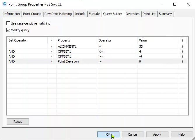
- Query Builder tab
- Point Group Properties dialog box
Create profile from points
- WisDOT Design tab > Design panel > Profile dropdown > Create Profile from Points
- Create Profile From Points dialog box
- Point Group = 33 SrvyCL
- Alignment = 33
- Profile Name = 33 SrvyCL
- Profile Style = PROF Existing
- Label Set Style = _No Labels
- OK
- Close when completed
- Create Profile From Points dialog box
-
See Profile - Create Profile from Points for more information on this tool.
Create profile view
- Home tab > Profile & Section View panel > Profile View dropdown > Create Profile View
- Create Profile View dialog box
- General
- Select alignment = 33
- Profile view name: PV-33-EB
- Profile view style = Stations 100' Major:50' Minor 1:10 Vert Ex
- Station Range
- User specified range = selected
- Start station = 490+00
- End station = 570+00
- Profile View Height
- Automatic = selected
- Profile Display Options
- 33 SrvyCL
- Draw = checked
- Labels = _No Labels
- 33 SrvyCL
- Data Bands
- Select band set = Elevation Both (Existing Left Proposed Right)
- Create Profile View
- CREATEPROFILEVIEW Select profile view origin
- Left-click the location where the lower left corner of the profile view will be placed
- NOTE: The profile view grid lines are located on layers E_PROF_Grid and E_PROF_GridMin and may be turned off to make it easier to see the sight distance profiles.
- CREATEPROFILEVIEW Select profile view origin
- General
- Create Profile View dialog box
-
Repeat the process and create another profile view named PV-33-WB
Check profile sight distance
dsn-chk-prfl-sit-dstnc-anlysis-02.mp4 6:02
Check eastbound profile sight distance
- WisDOT Design tab > Analyze panel > Visibility Check dropdown > Check Profile Sight Distance
- DOTCHECKPROFILESIGHTDISTANCE Select Profile View: select PV-33-EB profile view
- Profile Sight Distance dialog box
- Sight Lines
- Profile = 33 SrvyCL
- Start Station = 490+00
- End Station = 570+00
- If profile data DOES NOT exist at the analyzed sight distance, a sight line is drawn that is truncated to the profile data limits within the profile view.
- Check Increment (ft) = 25
- Sight Distance (ft) = 910, See FDM 11-10-5.1 Sight Distances
Object Height: 24 in (SSD), Stopping Sight Distance
- Output
- Create Report = checked
- File path = ProjectID\dsgn\check\SSDpc_33_EB_24IN_Exist_910
- Create Profile = checked
- Profile name = ASDpc_33_EB_24IN_Exist_910
- naming convention: Available Sight Distance profile check_ < Alignment name> _ < Direction of travel > _ < Object height > _ < Exist/Prop condition > _ < Sight distance analyzed >
- NOTE: The maximum available sight distance calculated is based on the Sight Distance value entered. Longer sight distances may be available based on the characteristics of the analyzed profile.
- Profile name = ASDpc_33_EB_24IN_Exist_910
- Create Sight Lines = checked
- Travel Direction for Layer Assignment: EB
- Create Report = checked
- OK
- Wait for analysis to be completed.
CLOSE
- Sight Lines
Check westbound profile sight distance
- WisDOT Design tab > Analyze panel > Visibility Check dropdown > Check Profile Sight Distance
- DOTCHECKPROFILESIGHTDISTANCE Select Profile View: select PV-33-WB profile view
- Profile Sight Distance dialog box
- Sight Lines
- Profile = 33 SrvyCL
- Start Station = 570+00
- End Station = 490+00
- Check Increment (ft) = 25
- Sight Distance (ft) = 910, See FDM 11-10-5.1 Sight Distances
- Object Height: 24 in (SSD), Stopping Sight Distance
- Output
- Create Report = checked
- File path = ProjectID\dsgn\check\SSDpc_33_WB_24IN_Exist_910
- Create Profile = checked
- Profile name = ASDpc_33_WB_24IN_Exist_910
- Create Sight Lines = checked
- Travel Direction for Layer Assignment: WB
- Create Report = checked
- OK
- Wait for analysis to be completed
- CLOSE
- Sight Lines
-
See Visibility Check - Check Profile Sight Distance for more information on this tool.
Create Available Sight Distance (ASD) profile view
Create profile view
- Home tab > Profile & Section View panel > Profile View dropdown > Create Profile View
- Create Profile View dialog box
- General
- Select alignment = 33
- Profile view name = ASDpc-33-EB
- Profile view style = Sight Distance
- Station Range
- User specified range = selected
- Start station = 490+00
- End station = 570+00
- User specified range = selected
- Profile View Height
- User specified = selected
- Minimum = 0.00'
- Maximum = 1700'
- Note that for this analysis the profile height represents sight distance and not an elevation
- Profile Display Options
- ASDpc_33_EB_24IN_Exist_910
- Draw = checked
- Labels = _No Labels
- Draw box for the other profiles = unchecked
- ASDpc_33_EB_24IN_Exist_910
- Data Bands
- Select band set = Sight Distance
- Create Profile View
- CREATEPROFILEVIEW Select profile view origin
- Left-click the location where the lower left corner of the profile view will be placed
- CREATEPROFILEVIEW Select profile view origin
- General
- Create Profile View dialog box
Update profile band
- Left-click to select the ASDpc-33-EB profile view > right-click > Profile View Properties... > Bands tab
- Profile View Properties dialog box
- Bands tab
- Style = Distance Left (Available Sight Distance)
- Profile1 = ASDpc_33_EB_24IN_Exist_910
- Style = Distance Right (Stopping Sight Distance)
- Show Labels = unchecked
- Style = Distance Left (Available Sight Distance)
- OK
- Bands tab
- Profile View Properties dialog box
- Repeat the process and create another profile view named ASDpc-33-WB
- Save the file