LnExtendBase - Version: 26.0
Last updated: 2026-01-06
ln-xtnd-base-01.mp4 11:30
 Description
Generic lane subassembly with one pavement layer, up to three base layers, and one subgrade improvement layer. Slope of pavement and subgrade can be independently fixed or controlled by superelevation. Base layer slopes can be oriented parallel to Top or Datum. The base layers can be extended beyond the pavement limits for use with curb and gutter. Divided highway support is provided by utilizing opposite side superelevation values multiplied by -1. This subassembly also includes a zero-pavement width option for creating a single set of break lines along a baseline or modeling curb and gutter without lanes.
Behavior
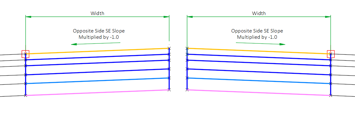
This subassembly is designed to accommodate modeling roadway lanes per WisDOT standards. All lane insertions allow the user to specify the use of the Insertion side Outside lane, Inside lane, Outside shoulder, or Inside shoulder superelevation slope as obtained from the superelevation specifications for the baseline alignment, or the use of the Outside lane, Inside lane, Outside shoulder, or Inside shoulder superelevation slope defined for the opposite side, which is then multiplied by -1.
The opposite side Outside/Inside lane/shoulder superelevation slope is used when creating assemblies for divided highways. On divided highways, the superelevation rotation point is defined at the inside edge of pavement. In normal crown the slope of the inside lane is upward at a 2% slope (+2%) which is achieved by using the Opposite side outside lane multiplied by –1. The outside lane would use the insertion side Outside lane SE slope to create a lane which slopes downward at 2%, thereby creating a roadway section that appears to rotate about the centerline in normal crown.
Starting at the attachment point, a finished pavement surface and subsequent base course surfaces are inserted using the given width, depth and slopes. Vertical links close the shape at either end of the lane.
There are two options for targeting a profile for the lane slope and elevation. The first option is to target a profile to set the elevation of the lane edge. The second option is to target a profile and interpret the profile elevation as a lane slope. The hierarchy for lane slope control is as follows: A profile target use to set lane slope supersedes any assigned superelevation or user-defined lane slope values. A profile target used to set lane elevation supersedes a profile target used to set lane slope and any assigned superelevation or user-defined lane slope values.
Alternatively, a marked point can be established in the same assembly group. Then, the subassembly can target the marked point to establish the outside lane elevation.
A targeted horizontal chain can be used to vary the width of the lane. Profiles can also be targeted to control the lane width and the inside/outside base extension widths. The profile elevation values are interpreted as width values. When targeted, these profiles supersede horizontal targets for width.
The subgrade slope is controlled by the Subgrade SE Method parameter. If Subgrade superelevation method is set to Use outside lane SE, inside lane SE, outside shoulder SE, or inside shoulder SE, the slope of the subgrade is equal to insertion side outside lane, inside lane, outside shoulder, or inside shoulder superelevation slope for the defined baseline alignment. If Subgrade superelevation method is set to Use the opposite side outside lane SE x -1, Use the opposite side inside lane SE x -1, Use opposite outside lane SE x -1, Use opposite side outside shoulder SE x -1, or Use opposite side inside shoulder SE x -1, the slope of the subgrade is equal to the opposite of insertion side outside lane, inside lane, outside shoulder, or inside shoulder superelevation slope multiplied by -1 for the defined baseline alignment. If Subgrade superelevation method is set to Follow pavement, then the subgrade slope will always be equal to the slope of the pavement surface, even if a target elevation is used to define the outer edge of the top of the travel lane. User also has the option of specifying a User defined slope.
A target profile elevation can be interpreted as the subgrade slope. The targeted profile always supersedes any superelevation or user-defined subgrade slope value.
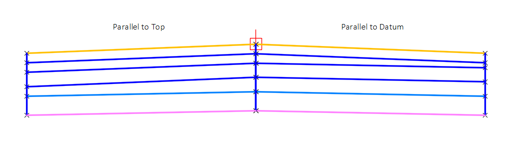
When the slope of the subgrade differs from the slope of the pavement surface, the user may use the Base layer slope orientation parameter to have all other base course layers follow the slope of the datum (subgrade) surface or follow the slope of the top (pavement) surface.
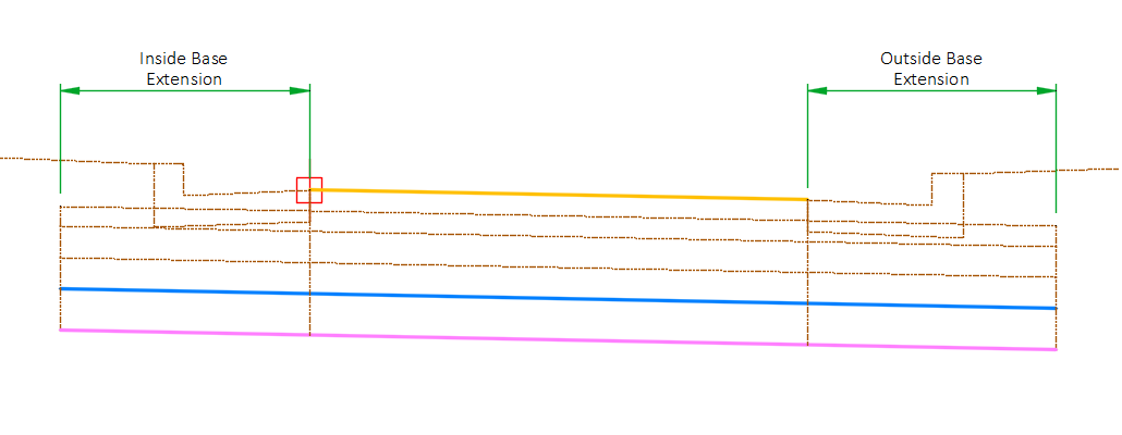
The subassembly may be used with a curb and gutter subassembly (such as CGBasic or UrbanCurbGutterGeneral) by extending the base layers beyond the pavement limits using the Inside base extension width and Outside Base extension width parameters. When these values are set to 0, the base width is equal to the pavement width. These parameters are only available when the pavement thickness in uniform (Inside pavement thickness = Outside pavement thickness) and non-zero.
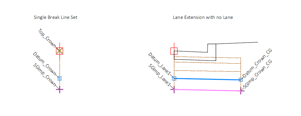
The subassembly also has a zero-pavement width option used for creating a single set of break lines along a baseline or where curb and gutter is desired without a lane. This is achieved by setting the Lane width parameter to 0. Note that in order to utilize the extended base feature for the curb and gutter, the Inside pavement thickness and Outside pavement thickness must be equal and non-zero.
Attachment & layout mode operation
The attachment point is at the inside edge of lane on the finish grade surface. This component can be attached to either the left or right side.
In layout mode, this subassembly displays the links using the given width and depths. The subassembly will display the pavement slope at the value given for the Pavement slope parameter. The subgrade slope will be displayed as the value given for the Subgrade slope parameter.
Input parameters
Info: All dimensions are in feet unless otherwise noted. All slopes are indicated as a percent slope with a "%" sign.
| Parameter | Description | Type | Default |
|---|---|---|---|
| Side | Indicates which side the subassembly is inserted towards. | Left/Right | Right |
| Lane width | Width of the lane from the offset of the inside edge to the offset of the outside edge. | Numeric, positive | 12.0 |
| Marked point | Name of marked point used establish outside lane elevation | String | MarkedPoint |
| Inside pavement thickness | Thickness of the inside edge of the pavement layer. | Numeric, positive | 0.375' |
| Outside pavement thickness | Thickness of the outside edge of the pavement layer | Numeric, positive | 0.375' |
| Base1 thickness | Thickness first base course layer. | Numeric, positive | 1.0' |
| Base2 thickness | Thickness second base course layer. | Numeric, positive | 0.0' |
| Subbase thickness | Thickness of subbase layer. | Numeric, positive | 0.0' |
| Subgrade improvement thickness | Thickness of subgrade improvement layer. | Numeric, positive | 0.0' |
| Superelevation type |
|
String, Combo List of options:
|
Use Outside Lane SE |
| Crown location | Specifies whether to code inside or outside edge of travelway as Crown. |
String, Combo List of options:
|
Inside |
| Pavement slope | User defined slope of the lane, used when the superelevation slope of the alignment is not defined or User defined is selected for Superelevation Type. | Slope | -2% |
| Subgrade SE method | Specifies to the method used to determine the slope of the subgrade surface. |
String, Combo List of options:
|
Follow Pavement |
| Subgrade slope | Default cross slope of the subgrade. This value is used if User defined is selected as the Subgrade SE Method or superelevation is not specified for the baseline alignment. | Slope | -2.0% |
| Base layer slope orientation | When multiple base layers exist, and entry of Parallel to top causes base layers to follow pavement (top) slope. Entry of Parallel to datum causes base layer to follow subgrade slope. |
String, Combo List of options:
|
Parallel to top |
| Inside base extension width | Width of base extension to the inside direction from the inside edge. | Numeric, positive | 0.0' |
| Outside base extension width | Width of base extension to the outside direction from the outside edge. | Numeric, positive | 0.0' |
| Include surface widening points | Yes/No | No | |
| Right point suffix | List of options to use for adding a suffix to all point codes on the right side. The user defined option uses the value of the “Right user defined point suffix” parameter. |
String, Combo
List of Options: NoSuffix PointCodeNumber |
_R |
| Left point suffix | List of options to use for adding a suffix to all point codes on the left side. The user defined option uses the value of the “Left user defined point suffix” parameter. | String, Combo List of Options: UserDefined _L _NB_L _SB_L _EB_L _WB_L _NW_L _NE_L _SW_L _SE_L _MED_L NoSuffix PointCodeNumber |
_L |
| Right user defined point suffix | User defined right point code suffix | String | |
| Left user defined point suffix | User defined left point code suffix | String |
Target parameters
This section lists the parameters in this subassembly that can be mapped to a target object such as a surface, alignment, or profile object in a drawing. For more information, see Setting and Editing Targets in the AutoCAD Civil 3D User's Guide Help.
| Parameter | Description | Status |
|---|---|---|
| Lane profile | May be used to override the normal lane slope and tie the outer edge of the travel lane to the elevation of an object. The following object types can be used as targets for specifying this elevation: profiles, 3D polylines, feature lines, or survey figures. | Optional |
| Lane slope from profile | May be used to override the normal lane slope by interpreting profile elevations as slope values. The following object types can be used as targets for specifying this elevation: profiles, 3D polylines, feature lines, or survey figures. | Optional |
| Lane width from profile | May be used to override the lane width by interpreting profile elevations as width values. The following object types can be used as targets for specifying this elevation: profiles, 3D polylines, feature lines, or survey figures. | Optional |
| Lane width | May be used to override the fixed lane width and tie the edge of a lane to an offset object. If insertion side is right, the object must be located to the right of the attachment point. If insertion side is left, the object must be located to the left of the attachment point. The following object types can be used as targets for specifying the width: alignments, polylines, feature lines, or survey features. | Optional |
| Subgrade slope from profile | May be used to override the normal subgrade slope by interpreting profile elevations as slope values. The following object types can be used as targets for specifying this elevation: profiles, 3D polylines, feature lines, or survey figures. | Optional |
| Inside base extension from profile | May be used to override the inside base extension width by interpreting profile elevations as width values. The following object types can be used as targets for specifying this elevation: profiles, 3D polylines, feature lines, or survey figures. | Optional |
| Outside base extension from profile | May be used to override the outside base extension width by interpreting profile elevations as width values. The following object types can be used as targets for specifying this elevation: profiles, 3D polylines, feature lines, or survey figures. | Optional |
| Inside base extension width | May be used to override the user defined base extension width on the inside. If insertion side is right, the object must be located to the left of the attachment point. If insertion side is left, the object must be located to the right of the attachment point. The following object types can be used as targets for specifying the width: alignments, polylines, feature lines, or survey features. | Optional |
| Outside base extension width | May be used to override the user defined base extension width on the inside. If insertion side is right, the object must be located to the right of the attachment point. If insertion side is left, the object must be located to the left of the attachment point. The following object types can be used as targets for specifying the width: alignments, polylines, feature lines, or survey features. | Optional |
| Surface for widening |
Output parameters
| Parameter | Description | Type |
|---|---|---|
| Offset of edge of lane [Output] | Offset of edge of top of pavement | Numeric |
| Lane width [Output] | Width of lane | Numeric |
| Inside base extension width [Output] | Width of base extension on the inside | Numeric |
| Outside base extension width [Output] | Width of base extension on the outside | Numeric |
| Pavement slope [Output] | Slope of the Pavement | Slope |
| Subgrade slope [Output] | Slope of the Subgrade Surface | Slope |
| Inside pavement thickness [Output] | Inside thickness of pavement | Numeric |
| Inside Base1 thickness [Output] | Base1 thickness at inside Edge computed by taking the difference between the elevation at P5 and P3. | Numeric |
| Inside Base2 thickness [Output] | Base2 thickness at inside Edge computed by taking the difference between the elevation at P7 and P5. | Numeric |
| Inside Subbase thickness [Output] | Subbase Thickness at inside Edge computed by taking the difference between the elevation at P9 and P7. | Numeric |
| Outside pavement thickness [Output] | Outside thickness of pavement | Numeric |
| Outside Base1 thickness [Output] | Base1 thickness at outer Edge computed by taking the difference between the elevation at P6 and P4. | Numeric |
| Outside Base2 thickness [Output] | Base2 thickness at outer Edge computed by taking the difference between the elevation at P8 and P6. | Numeric |
| Outside Subbase thickness [Output] | Subbase Thickness at outer Edge computed by taking the difference between the elevation at P10 and P8. | Numeric |
| Subgrade Improvement thickness [Output] | Thickness of the subgrade improvement | Numeric |
| Inside subgrade depth [Output] | Depth to Subgrade Surface at inner Edge computed by taking the difference between the elevation at P11 and P9. | Numeric |
| Outside subgrade depth [Output] | Depth to Subgrade Surface at outer Edge computed by taking the difference between the elevation at P12 and P10. | Numeric |
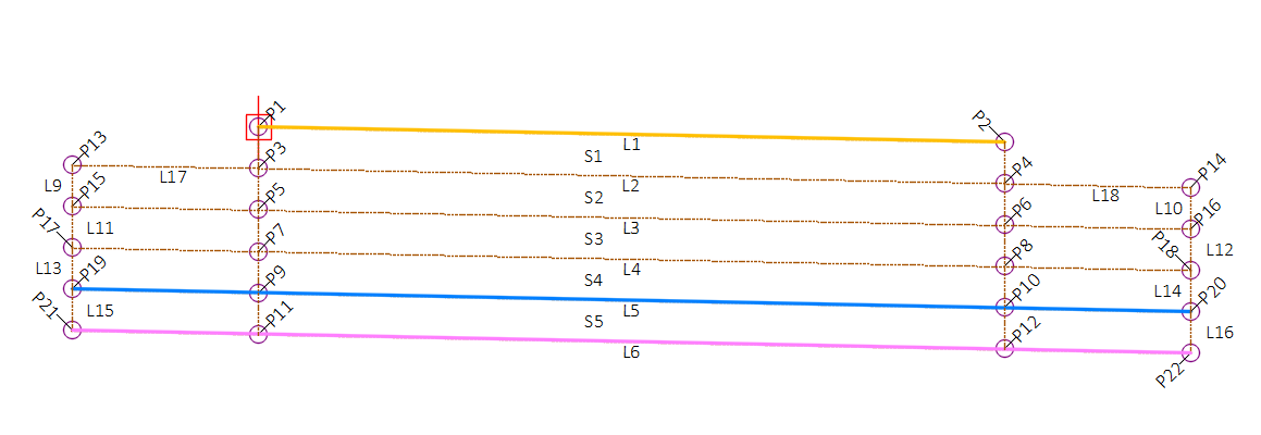
Point, Link, and Shape codes
| Point/Link/Shape | Codes | Description |
|---|---|---|
| P1 |
Top_Crown |
Crown point or edge of lane point on finish grade |
| P2 |
Top_Lane1 |
Edge of lane point or crown point on finish grade |
| P3 | Pave1_Crown | Crown point or edge of lane point at bottom of pavement layer (optional) |
| P4 | Pave1_Lane1 | Edge of lane or crown point at bottom of pavement layer (optional) |
| P5 | =Base1_Crown | Crown point or edge of lane point at bottom of Base1 layer (optional) |
| P6 | Base1_Lane1 | Outside edge of lane point or crown point at bottom of Base1 layer (optional) |
| P7 | =Base2_Crown | Crown point or edge of lane point at bottom of Base2 layer (optional) |
| P8 | Base2_Lane1 | Edge of lane point or crown point at bottom of Base2 layer (optional) |
| P9 | =Datum_Crown | Crown point or edge of lane point on subgrade |
| P10 | Datum_Lane1[ ] | Edge of lane point or crown point on subgrade |
| P11 | =SGImp_Crown | Crown point or edge of lane point on bottom of subgrade improvement (optional) |
| P12 | SGImp_Lane1[ ] | Edge of lane point or crown point on bottom of subgrade improvement (optional) |
| P13 | =Pave1_Crown_CG[ ] | Top of first extended base layer on crown side or edge of lane side (optional) |
| P14 | Pave1_CG[ ] | Top of first extended base layer on edge of lane side or crown side (optional) |
| P15 | =Base1_Crown_CG[ ] | Bottom of extended Base1 layer on crown side or edge of lane side (optional) |
| P16 | Base1_CG[ ] | Bottom of extended Base1 layer on edge or lane side or crown side (optional) |
| P17 | =Base2_Crown_CG[ ] | Bottom of extended Base2 layer on crown side or edge of lane side (optional) |
| P18 | Base2_CG[ ] | Bottom of extended Base2 layer on edge or lane side or crown side (optional) |
| P19 | =Datum_Crown_CG | Extended subgrade point on Crown side or edge of lane side |
| P20 | Datum_CG | Extended subgrade point on edge of lane side or crown side |
| P21 | =SGImp_Crown_CG | Bottom of extended Subgrade Improvement layer on crown side or edge of lane side (optional) |
| P22 | SGImp_CG | Bottom of extended Subgrade Improvement layer on edge or lane side or crown side (optional) |
| P203 | Pave1_Crown_Widen | A point is added along Pave1 if it intersects the target surface |
| P205 | Base1_Crown_Widen | A point is added on Base1 if it intersects the target surface |
| P207 | Base2_Crown_Widen | A point is added on Base2 if it intersects the target surface |
| P209 | Datum_Crown_Widen | A point is added on Datum if it intersects the target surface |
| L1 | Top,LABELPCT,PaveLn1 | Finish grade |
|
L2, L17, L18 |
Pave1 | Bottom of pavement/top of base (optional) |
|
L3 |
Base1 | Bottom of first Base (optional) |
| L4 | Base2 | Bottom of second Base (optional) |
| L5 | LABELPCT, Datum | Subgrade |
| L6 | SGImp | Bottom of subgrade improvement (optional) |
| L7 | =PaveEdge_In[ ] | Inside edge of pavement (optional) |
| L8 | =PaveEdge_Out[ ] | Outside edge of pavement (optional) |
| L9, L11, L13, L15 | BaseEdge_In | Inside edge of base layers (optional) |
| L10, L12, L14, L16 | BaseEdge_Out | Outside edge of base layers (optional) |
| L19 | =NoDisplay[ ] | Inside pavement edge projection |
| L20 | =NoDisplay[ ] | Outside pavement edge projection |
| S1 | Pave1 | Pavement shape (optional) |
| S2 | Base1 | First base layer shape (optional) |
| S3 | Base2 | Second base layer shape (optional) |
| S4 | Subbase | Subbase layer shape (optional) |
| S5 | SG_Imp | Subgrade improvement shape (optional) |