CGBasic – Version 26.1
Last updated: 2026-06-04
Previous versions still in production can be found below current version
Total video time: 26:05
Summary of Inputs and Targets 7:39
Curb Sizes 2:42
Gutter Slope, Terrace, and Marked Point 2:12
Curb Size Overrides 1:51
Curb Return Assembly and Curb Transitions 2:40
Options for Creating Medians - 1 3:45
Description
The CGBasic subassembly inserts points, links and shapes representing standard WisDOT concrete curb and gutter types with optional base course layers and terrace options. Dimensions of the curb and gutter are fixed shapes per WisDOT standard details and select municipal standards.
The CGBasic subassembly does not have parameters for creating base and subbase layers. This subassembly can be partnered with the LnExtendBase subassembly by attaching it to the inside or outside top pavement point. The LnExtendBase has options to extend the base and subbase layers under the curb.
Behavior
Curb shape, gutter slope and dimensions are derived from WisDOT standard detail drawings as shown in the WisDOT Facilities Development Manual.
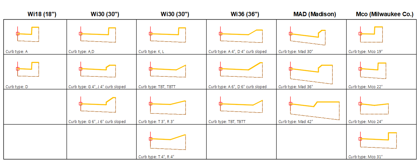
Curb Type
- WisDOT standard curb selection is determined by first setting the Curb and gutter size parameter to either Wi18, Wi30, or Wi36 and then setting the corresponding curb type parameter; Wi 18" Curb Types, Wi 30" Curb Types, Wi 36" Curb Types.
- Curb selection for Milwaukee County and City of Madison is determined by setting the Curb and gutter size parameter to one of the Mco# or Mad# options.
-
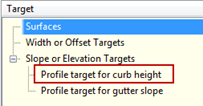
The Profile target for curb height can be assigned an elevation target (a profile that defines an elevation) during the corridor build process and will override the gutter type curb height, and allow for creating curb height transitions.
Gutter slope
Bottom of curb link is always parallel to the gutter slope.
- When Gutter slope method is set to Standard, the slope of the gutter will adhere to the standard detail slope.
- When Gutter slope method is set to User defined, the user may define a slope by setting the User defined slope parameter or, once an Assembly has been built, the user may set a parameter reference for the User defined slope in the Assembly Properties.
- When Gutter slope method is set to any SEoption, the subassembly uses the baseline alignment SE to determine the gutter slope. When using any of the "Use opposite" designated parameters, the gutter slope is defined from the SE slope on the opposite side, multiplied by -1.0. A profile elevation target can be used to create or adjust curb slope transition.
-
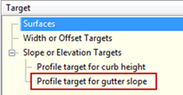
The Profile target for gutter slope can be assigned an elevation target (a profile that defines a slope as an elevation) during the corridor build process and will override any Gutter slope method parameter.
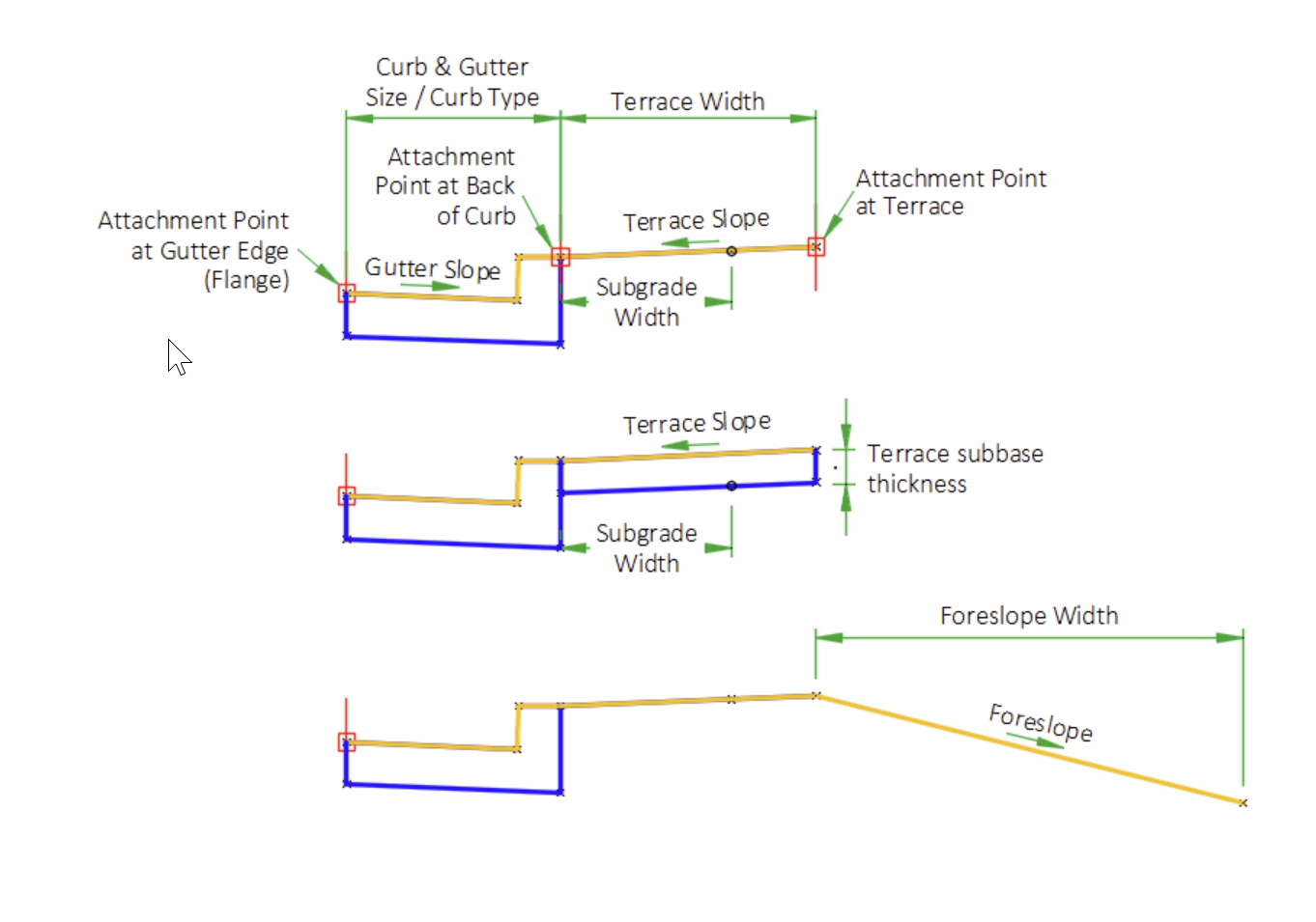
Terrace
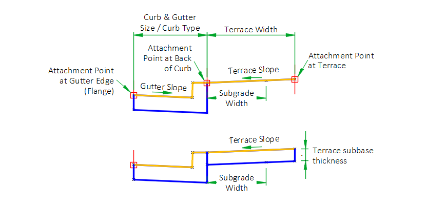
The terrace is a link and a point at the end of the link that is inserted at a width and slope from the back of the curb.
- Terrace width defines the total width of the terrace.
- Terrace slope defines the slope of the terrace or the slope of the extended subgrade top link.
- Subgrade width defines a width the subbase layer extends beyond the back of the curb.
- Terrace width input is less than Subgrade width input, a link is inserted from the back of curb for a distance defined by the Subgrade width and a slope defined by the Terrace slope.
- When the Terrace width input is greater than the Subgrade width, a point is inserted on the terrace link defined by the Subgrade width.
- When the Terrace width is set to zero, and the Subgrade width is set to zero, a terrace width of 0.01 is created to allow for datum surface creation needs.
-
Setting Add outside terrace link to marked point to Yes, creates the terrace link to a marked point. The marked point name is required in the Marked point target name parameter.
Terrace Subbase
The Terrace subbase thickness parameter can be set to define the thickness of the terrace subbase.
- When the Terrace width is not set to zero, links and a shape below the terraces link will be inserted.
- When a Subgrade width is defined the datum point will be inserted on the terrace subbase link instead of on the terrace (top) link.
Add foreslope point and link
When the Add foreslope point and link parameter is set to Yes, a link and point is create attached to the outside top terrace point (P7). This option may be used to assist with the foreslope transitions from a shoulder section to a curb section where the shoulder foreslope tapers into the curb terrace. It may also be used to continue the foreslope defined by the shoulder behind a rural curb return.
Define the slope of the foreslope
The Foreslope parameter value defines the slope of the foreslope link.
The Foreslope slope from profile target may be used to obtain the slope from a control profile.
Define the width of the foreslope
There are two options to define the width of the foreslope.
Assigning a horizontal target to the Foreslope width target within the corridor target interface.
Defined the foreslope width by using parameter references from the LnExtendBase subassembly. This option requires values be obtained through assigning parameter references for the Subgrade slope, Pave thickness, Base1 thickness, Base2 thickness, Subbase thickness parameters. This option will make the foreslope link function similar to a shoulder assembly by adhere to lane slope transitions and superelevation conditions.
Attachment & layout mode operation
The CGBasic has three attachment point options, at the gutter edge or flange, at the top back of the curb, or at the outside point of the terrace.
- When the Insertion point parameter is set to Gutter edge, the subassembly displays the curb & gutter component based on the parameters and targets selected.
- When the Insertion point parameter is set to Back of curb or Terrace, the subassembly displays the curb & gutter component based on the parameters selected, but the Profile target for curb height cannot be defined. The curb heights will remain at the selected curb type height.
Input parameters
Info: All dimensions are in feet unless otherwise noted. Curb & gutter dimensions are in inches. All slopes are in a percent slope designated with a "%" sign.
| Parameter | Description | Type | Default |
|---|---|---|---|
| Side | Indicates which side the subassembly is inserted towards. | Left/Right | Right |
| Insertion Point |
Combo List of options: Gutter edge ; Back of curb ; Terrace |
Gutter edge | |
| Curb and gutter size | Curb and gutter size is the horizontal distance from the back of curb to the flange of curb (inches). |
Combo List of options: WI18 ; WI30 ; WI36 ; Mco19 ; Mco22 ; Mco24 ; Mco31 ; Mad30 ; Mad36 ; Mad42 |
WI30 |
| Wi 18" curb types | Type of 18" WisDOT curb and gutter to construct. |
Combo List of options: A; D |
A |
| Wi 30" curb types | Type of 30" WisDOT curb and gutter to construct. The suffix "curb sloped" refers to the curb head. |
Combo List of options: A ; D ; G 4" curb sloped ; G 6" curb sloped ; J 4" curb sloped ; J 6" curb sloped ; K ; K optional curb ; L ; L optional curb; TBT/TBTT |
A |
| Wi 36" curb types | Type of 36" WisDOT curb and gutter to construct. The suffix "curb sloped" refers to the curb head. |
Combo List of options: A 4" curb sloped ; A 6" curb sloped ; D 4" curb sloped ; D 6" curb sloped ; R ; T; TBT/TBTT |
A 4" curb sloped |
| Gutter slope method | Specifies method of gutter slope calculation. |
Combo List of options:
|
Use Outside Lane SE |
| User defined slope | Specifies gutter slope when Gutter slope method is set to User defined. |
Slope |
-2.00% |
| Subgrade width | Distance the base/subbase courses are extended beyond the back-of-curb. Use zero to terminate the base/subbase courses at the back-of-curb. |
Numeric, Non-negative |
2.0' |
| Subgrade Overhang Correction | Additional offset of Subgrade width point for datum surface creation | Yes/No | Yes |
| Overhang distance | Offset distance used by the Subgrade overhang correction | Numeric, Non-negative | 0.01 |
| Terrace width | Width of the terrace, measured from the top of the back of curb. |
Numeric, Non-negative |
3.0 |
| Terrace slope | Slope of the terrace and top link of the Subgrade width if the Terrace width is set to zero. |
Slope |
4.00% |
| Terrace subbase thickness (inches) | Option to create a terrace subbase links and a shape. |
Numeric, Non-negative |
0.0" |
| Add outside terrace link to marked point | Option to create a terrace link to a marked point | Yes/No | No |
| Marked point target name | Name of marked point to target for terrace link | String | OTP |
| C&G size override | Override gutter width | Numeric, Non-negative | 0' |
| Curb width override | Override curb width | Numeric, Non-negative | 0' |
| Curb height override | Override curb height | Numeric, Non-negative | 0' |
| Gutter depth override | Override C&G depth | Numeric, Non-negative | 0' |
| Add foreslope point and link | Option to create a foreslope link attached to the outer terrace point. | Yes/No | No |
| Foreslope | Defines the slope of the foreslope link. | Slope | 4.00:1 |
| Subgrade slope (parameter reference) | Defines the adjacent lane subgrade slope value used to calculate the foreslope width. | Numeric, Non-negative | 4.5" |
| Pave thickness (parameter reference) | Defines the adjacent lane Pave thickness value used to calculate the foreslope width. | Numeric, Non-negative | 12" |
| Base1 thickness (parameter reference) | Defines the adjacent lane Base1 thickness value used to calculate the foreslope width. | Numeric, Non-negative | 0" |
| Base2 thickness (parameter reference) | Defines the adjacent lane Base2 thickness value used to calculate the foreslope width. | Numeric, Non-negative | 0" |
| Subbase thickness (parameter reference) | Defines the adjacent lane Subbase thickness value used to calculate the foreslope width. | Numeric, Non-negative | 0" |
| Right point suffix | List of options to use for adding a suffix to all point codes on the right side. The user defined option uses the value of the “Right user defined point suffix” parameter. |
String, Combo List of Options: NoSuffix PointCodeNumber |
_R |
| Left point suffix | List of options to use for adding a suffix to all point codes on the left side. The user defined option uses the value of the “Left user defined point suffix” parameter. | String, Combo List of Options: UserDefined _L _NB_L _SB_L _EB_L _WB_L _NW_L _NE_L _SW_L _SE_L _MED_L NoSuffix PointCodeNumber |
_L |
| Right user defined point suffix | User defined right point code suffix | String | |
| Left user defined point suffix | User defined left point code suffix | String |
Target parameters
These are the parameters in this subassembly that can be mapped to a target object such as a alignment, polyline, feature line, or survey feature object in a drawing. For more information, see Setting and Editing Targets in the AutoCAD Civil 3D User's Guide Help.
| Parameter | Description | Status |
|---|---|---|
| Terrace Width | May be used to override the terrace width and tie the outside edge of the terrace to an offset object. If insertion side is right, the object must be located to the right of the attachment point. If insertion side is left, the object must be located to the left of the attachment point. The following object types can be used as targets for specifying the width: alignments, polylines, feature lines, or survey features. | Optional |
| Curb height from profile | May be used to override the curb height and tie the curb height to a profile. The profile should be designed so the profile elevations define the curb height. | Optional |
| Gutter slope from profile | May be used to override the gutter slope and tie the gutter slope to a profile. The profile should be designed so the profile elevations defines a slope. | Optional |
| Terrace profile | May be used to override the terrace slope and tie the outer edge of the terrace to the elevation of an object. The following object types can be used as targets for specifying this elevation: profiles, 3D polylines, feature lines, or survey figures. | Optional |
| Terrace slope from profile | May be used to override the terrace slope and tie the terrace slope to a profile. The profile should be designed so the profile elevations define a slope. | Optional |
| Terrace width from profile | May be used to override the terrace width and tie the terrace width to a profile. The profile should be designed so the profile elevations defines a width. | Optional |
| Subgrade width | May be used to override the subgrade width and tie the subgrade width to an offset object. If insertion side is right, the object must be located to the right of the attachment point. If insertion side is left, the object must be located to the left of the attachment point. The following object types can be used as targets for specifying the width: alignments, polylines, feature lines, or survey features. | Optional |
| Subgrade width from profile | May be used to override the subgrade width and tie the subgrade width to a profile. The profile should be designed so the profile elevations defines a width. | Optional |
| Foreslope width | May be used to override the foreslope width calculation and tie the foreslope width to an offset object. If insertion side is right, the object must be located to the right of the attachment point. If insertion side is left, the object must be located to the left of the attachment point. The following object types can be used as targets for specifying the width: alignments, polylines, feature lines, or survey features. | Optional |
| Foreslope slope from profile | May be used to override the Foreslope slope and tie the slope to a profile. The profile should be designed so the profile elevations defines a slope. | Optional |
Output parameters
Info: All dimensions are in feet unless otherwise noted. Slopes are in a percent slope designated with a "%" sign.
| Parameter | Description | Type |
|---|---|---|
| Curb and gutter width [Output] | Full width of curb and gutter. | Numeric |
| Curb height [Output] | Curb head height. | Numeric |
| Gutter width [Output] | Width from the curb flange to the curb flow line. | Numeric |
| Gutter slope [Output] | Curb gutter slope. | Slope |
| Foreslope [Output] | Slope of the foreslope link. | Numeric |
| Subgrade width [Output] | Width of the subgrade extended behind the curb. | Numeric |
| Terrace slope [Output] | Slope of the terrace and top of subgrade width if the terrace width is set to zero. | Slope |

Point, Link, and Shape codes
| Point/Link/Shape | Codes | Description |
|---|---|---|
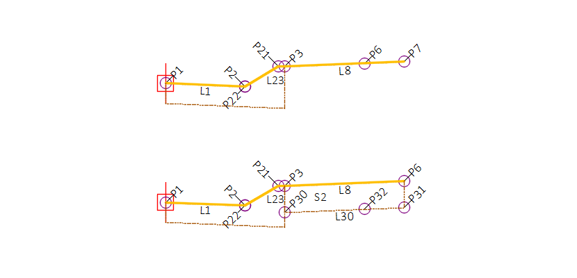
| P1 | Top_Flange | Flange point of the gutter |
| P2 | Top_FL | Gutter flowline point |
| P21 | Top_TC[] | Top of curb point |
| P22 | Top_FC[] | Face of curb point |
| P3 | Top_BC | Top back of curb point |
| P4 | Flange curb base | |
| P5 | Back of curb base | |
| P6 | Datum_CG_Terrace,Top_CG_Terrace | Subgrade width point on top terrace link, or on bottom of terrace subgrade if a terrace subgrade thickness is defined. |
| P7 | TopDatum_Terrace | Terrace top end point |
| P9 | TopDatum_Terrrace_Out[] | Outside point, link to marked point |
| P30 | Inside terrace subgrade point | |
| P31 | Datum_Sub_Out | Outside terrace subgrade point |
| P32 | Attach_out | Foreslope intercept point |
| L1 | Top,Gutter | Link from flange to flowline |
| L2 | Top,CrbFc | Curb face |
| L21 | Top,CrbFc | Top of curb link |
| L22 | Top,CrbTprFc | Face of curb link |
| L23 | Top,TopOfCrb | Taper of curb face link |
| L3-L5 | BaseOfCrb[] | Base of curb |
| L8 | Top,CGTrc,LABELPCT | Top of terrace |
| L9 | TopDatum,CGTrcLnk | Link to marked point |
| L30 | Terrace_Sub | Subbase terrace link |
| L31 | Edge | Outside depth of terrace subbase |
| L32 | Edge | Inside depth of terrace subbase |
| L33 | TopDatum,Fslp,LABELSLP | TopDatum foreslope |
| S1 | Curb | Curb |
| S2 | TrcSubbase | Terrace subgrade |
CGBasic – Version 26.0
 Description
The CGBasic subassembly inserts points, links and shapes representing standard WisDOT concrete curb and gutter types with optional base course layers and terrace options. Dimensions of the curb and gutter are fixed shapes per WisDOT standard details and select municipal standards.
The CGBasic subassembly does not have parameters for base and subbase layers. This subassembly can be partnered with the LnExtendBase subassembly by attaching it to the inside or outside top pavement point. The LnExtendBase has options to extend the base and subbase layers under the curb.
Behavior
Curb shape, gutter slope and dimensions are derived from WisDOT standard detail drawings as shown in the WisDOT Facilities Development Manual.
Curb Type
- WisDOT standard curb selection is determined by first setting the Curb and gutter size parameter to either Wi18, Wi30, or Wi36 and then setting the corresponding curb type parameter; Wi 18" Curb Types, Wi 30" Curb Types, Wi 36" Curb Types.
- Curb selection for Milwaukee County and City of Madison is determined by setting the Curb and gutter size parameter to one of the Mco# or Mad# options.
-
The Profile target for curb height can be assigned an elevation target (a profile that defines an elevation) during the corridor build process and will override the gutter type curb height, and allow for creating curb height transitions.
Gutter slope
Bottom of curb link is always parallel to the gutter slope.
- When Gutter slope method is set to Standard, the slope of the gutter will adhere to the standard detail slope.
- When Gutter slope method is set to User defined, the user may define a slope by setting the User defined slope parameter or, once an Assembly has been built, the user may set a parameter reference for the User defined slope in the Assembly Properties.
- When Gutter slope method is set to any SEoption, the subassembly uses the baseline alignment SE to determine the gutter slope. When using any of the "Use opposite" designated parameters, the gutter slope is defined from the SE slope on the opposite side, multiplied by -1.0. A profile elevation target can be used to create or adjust curb slope transition.
-
The Profile target for gutter slope can be assigned an elevation target (a profile that defines a slope as an elevation) during the corridor build process and will override any Gutter slope method parameter.
Terrace
The terrace is a link and a point at the end of the link that is inserted at a width and slope from the back of the curb.
- Terrace width defines the total width of the terrace.
- Terrace slope defines the slope of the terrace or the slope of the extended subgrade top link.
- Subgrade width defines a width the subbase layer extends beyond the back of the curb.
- Terrace width input is less than Subgrade width input, a link is inserted from the back of curb for a distance defined by the Subgrade width and a slope defined by the Terrace slope.
- When the Terrace width input is greater than the Subgrade width, a point is inserted on the terrace link defined by the Subgrade width.
- When the Terrace width is set to zero, and the Subgrade width is set to zero, a terrace width of 0.01 is created to allow for datum surface creation needs.
-
Setting Add outside terrace link to marked point to Yes, creates the terrace link to a marked point. The marked point name is required in the Marked point target name parameter.
Terrace Subbase
The Terrace subbase thickness parameter can be set to define the thickness of the terrace subbase.
- When the Terrace width is not set to zero, links and a shape below the terraces link will be inserted.
- When a Subgrade width is defined the datum point will be inserted on the terrace subbase link instead of on the terrace (top) link.
Attachment & layout mode operation
The CGBasic has three attachment point options, at the gutter edge or flange, at the top back of the curb, or at the outside point of the terrace.
- When the Insertion point parameter is set to Gutter edge, the subassembly displays the curb & gutter component based on the parameters and targets selected.
- When the Insertion point parameter is set to Back of curb or Terrace, the subassembly displays the curb & gutter component based on the parameters selected, but the Profile target for curb height cannot be defined. The curb heights will remain at the selected curb type height.
Input parameters
Info: All dimensions are in feet unless otherwise noted. Curb & gutter dimensions are in inches. All slopes are in a percent slope designated with a "%" sign.
| Parameter | Description | Type | Default |
|---|---|---|---|
| Side | Indicates which side the subassembly is inserted towards. | Left/Right | Right |
| Insertion Point |
Combo List of options: Gutter edge ; Back of curb ; Terrace |
Gutter edge | |
| Curb and gutter size | Curb and gutter size is the horizontal distance from the back of curb to the flange of curb (inches). |
Combo List of options: WI18 ; WI30 ; WI36 ; Mco19 ; Mco22 ; Mco24 ; Mco31 ; Mad30 ; Mad36 ; Mad42 |
WI30 |
| Wi 18" curb types | Type of 18" WisDOT curb and gutter to construct. |
Combo List of options: A; D |
A |
| Wi 30" curb types | Type of 30" WisDOT curb and gutter to construct. The suffix "curb sloped" refers to the curb head. |
Combo List of options: A ; D ; G 4" curb sloped ; G 6" curb sloped ; J 4" curb sloped ; J 6" curb sloped ; K ; K optional curb ; L ; L optional curb; TBT/TBTT |
A |
| Wi 36" curb types | Type of 36" WisDOT curb and gutter to construct. The suffix "curb sloped" refers to the curb head. |
Combo List of options: A 4" curb sloped ; A 6" curb sloped ; D 4" curb sloped ; D 6" curb sloped ; R ; T; TBT/TBTT |
A 4" curb sloped |
| Gutter slope method | Specifies method of gutter slope calculation. |
Combo List of options:
|
Use Outside Lane SE |
| User defined slope | Specifies gutter slope when Gutter slope method is set to User defined. |
Slope |
-2.00% |
| Subgrade width | Distance the base/subbase courses are extended beyond the back-of-curb. Use zero to terminate the base/subbase courses at the back-of-curb. |
Numeric, Non-negative |
2.0' |
| Subgrade Overhang Correction | Additional offset of Subgrade width point for datum surface creation | Yes/No | Yes |
| Overhang distance | Offset distance used by the Subgrade overhang correction | Numeric, Non-negative | 0.01 |
| Terrace width | Width of the terrace, measured from the top of the back of curb. |
Numeric, Non-negative |
3.0 |
| Terrace slope | Slope of the terrace and top link of the Subgrade width if the Terrace width is set to zero. |
Slope |
4.00% |
| Terrace subbase thickness (inches) | Option to create a terrace subbase links and a shape. |
Numeric, Non-negative |
0.0" |
| Add outside terrace link to marked point | Option to create a terrace link to a marked point | Yes/No | No |
| Marked point target name | Name of marked point to target for terrace link | String | OTP |
| C&G size override | Override gutter width | Numeric, Non-negative | 0 |
| Curb width override | Override curb width | Numeric, Non-negative | 0 |
| Curb height override | Override curb height | Numeric, Non-negative | 0 |
| Gutter depth override | Override C&G depth | Numeric, Non-negative | 0 |
| Right point suffix | List of options to use for adding a suffix to all point codes on the right side. The user defined option uses the value of the “Right user defined point suffix” parameter. |
String, Combo
List of Options: NoSuffix PointCodeNumber |
_R |
| Left point suffix | List of options to use for adding a suffix to all point codes on the left side. The user defined option uses the value of the “Left user defined point suffix” parameter. | String, Combo List of Options: UserDefined _L _NB_L _SB_L _EB_L _WB_L _NW_L _NE_L _SW_L _SE_L _MED_L NoSuffix PointCodeNumber |
_L |
| Right user defined point suffix | User defined right point code suffix | String | |
| Left user defined point suffix | User defined left point code suffix | String |
Target parameters
These are the parameters in this subassembly that can be mapped to a target object such as a alignment, polyline, feature line, or survey feature object in a drawing. For more information, see Setting and Editing Targets in the AutoCAD Civil 3D User's Guide Help.
| Parameter | Description | Status |
|---|---|---|
| Terrace Width | May be used to override the terrace width and tie the outside edge of the terrace to an offset object. If insertion side is right, the object must be located to the right of the attachment point. If insertion side is left, the object must be located to the left of the attachment point. The following object types can be used as targets for specifying the width: alignments, polylines, feature lines, or survey features. | Optional |
| Curb height from profile | May be used to override the curb height and tie the curb height to a profile. The profile should be designed so the profile elevations define the curb height. | Optional |
| Gutter slope from profile | May be used to override the gutter slope and tie the gutter slope to a profile. The profile should be designed so the profile elevations defines a slope. | Optional |
| Terrace profile | May be used to override the terrace slope and tie the outer edge of the terrace to the elevation of an object. The following object types can be used as targets for specifying this elevation: profiles, 3D polylines, feature lines, or survey figures. | Optional |
| Terrace slope from profile | May be used to override the terrace slope and tie the terrace slope to a profile. The profile should be designed so the profile elevations define a slope. | Optional |
| Terrace width from profile | May be used to override the terrace width and tie the terrace width to a profile. The profile should be designed so the profile elevations defines a width. | Optional |
| Subgrade width | May be used to override the subgrade width and tie the subgrade width to an offset object. If insertion side is right, the object must be located to the right of the attachment point. If insertion side is left, the object must be located to the left of the attachment point. The following object types can be used as targets for specifying the width: alignments, polylines, feature lines, or survey features. | |
| Subgrade width from profile | May be used to override the subgrade width and tie the subgrade width to a profile. The profile should be designed so the profile elevations defines a width. |
Output parameters
Info: All dimensions are in feet unless otherwise noted. Slopes are in a percent slope designated with a "%" sign.
| Parameter | Description | Type |
|---|---|---|
| Subgrade width [Output] | Width of the subgrade extended behind the curb. | Numeric |
| Terrace slope [Output] | Slope of the terrace and top of subgrade width if the terrace width is set to zero. | Slope |
Point, Link, and Shape codes
| Point/Link/Shape | Codes | Description |
|---|---|---|
| P1 | Top_Flange | Flange point of the gutter |
| P2 | Top_FL | Gutter flowline point |
| P21 | Top_TC | Top of curb point |
| P22 | Top_FC | Face of curb point |
| P3 | Top_BC | Top back of curb point |
| P4 | Flange curb base | |
| P5 | Back of curb base | |
| P6 | Datum_CG_Terrace,Top_CG_Terrace | Subgrade width point on top terrace link, or on bottom of terrace subgrade if a terrace subgrade thickness is defined. |
| P7 | TopDatum_Terrace | Terrace top end point |
| P9 | TopDatum_Terrrace_Out | Outside point, link to marked point |
| P30 | Inside terrace subgrade point | |
| P31 | Datum_Sub_Out | Outside terracesubgrade point |
| P32 | Datum_Sub_In | Terrace subbase datum point |
| L1 | Top, Gutter | Link from flange to flowline |
| L2 | Top, CrbFc | Curb face |
| L21 | Top, CrbFc | Top of curb link |
| L22 | Top, CrbTprFc | Face of curb link |
| L23 | Top, TopOfCrb | Taper of curb face link |
| L3-L5 | BaseOfCrb | Base of curb |
| L8 | LABELPCT, Top, CGTrc | Top of terrace |
| L9 | TopDatum, CGTrcLnk | Link to marked point |
| L30 | Terrace_Sub | Subbase terrace link |
| L31 | Edge | Outside depth of terrace subbase |
| L32 | Edge | Inside depth of terrace subbase |
| S1 | Curb | Curb |
| S2 | TrcSubbase | Terrace subgrade |