Cross sections: how to control size and layout
Last updated: 2026-01-06
Total video time: 19:15
 Object and style information
xsec-cntrl-sz-lyout-01.mp4 4:14
- Object structure
- Alignment > Sample lines > Sections > Section View Groups
- Impacts
- There cannot be sections on different alignments in the same section view group
- Sample lines are based on the alignment, go left and right, and cannot be negative (i.e. you cannot have a section with offsets from -150 to -10)
- Section view group important details (this is where all the good stuff is at)
- Station range: do not need to pick entire station range of sample lines at the same time
- Section view style and cross section sheet template: where scale is set
- Offset range: inherited from sample lines
- Elevation range: this combined with scale determines how many sections are on a sheet
- Automatic: Good for a station range with large variation in section height. Has a tendency to use a LOT of space.
User specified: Good for controlling number of sections per sheet
Info: Both of these options start the minimum elevation at a major interval. i.e. if the major interval is 10 FT, the section minimum elevation will be 1170 FT or 1180 FT, but never 1175 FT or 1172 FT.
Section view height option: Determines section height with automatic option. Determines minimum and maximum based on selection for both options.
- Paper dimensions for cross section sheet
- Grid area: 15.75 IN wide x 9.75 IN high
- Buffer between section views: 0.5 IN
Tip: These are not the only possible section heights. They are only showing a sample of possible combinations. Manual section heights are recommended to be in increments of 5 FT.
Create and adjust section view group height and layout
xsec-cntrl-sz-lyout-02.mp4 7:32
090101-xs.dwg
- XREF corridor file
- Six sample lines
- ANNOSCALE: 1 IN:10 FT
Create section view group
- Home tab > Profile & Section Views panel > Section views > Create multiple views
- General
- Select alignment: 25
- Sample line group name: SLG-2
- Station range: Automatic
- Section view style: Sheets 1 IN 10 FT Horiz 10 FT Vert
- Next >
- Section Placement
- Placement Options: Production C:\wisdot\stnd\c3d2018\templates\sheets\09-XS-wdot18.dwt|XS 1IN 10FT Horiz 10FT Vert
- Group Plot Style: By Page (Bottom to Top)
- Next >
- Offset Range
- Automatic: checked
- Next >
- Elevation Range
- Automatic: checked
- Create Section View
- General
- Click in modelspace
This will create 2 section sheets with 6 sections of varying height. All sections start and end at intervals of 10 FT. Let's try fitting more sections on the first sheet.
Set user-defined height of sections
- Toolspace > Prospector > Right-click Section View Group - 1 > Properties...
- Section views tab > Offset and Elevation > ...
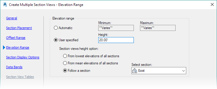
- Elevation Range: User Specified
- Height: 20'
- Section views height option: From mean elevation of all sections
- OK
- OK
- Section views tab > Offset and Elevation > ...
- Toolspace > Prospector > Right-click Section View Group - 1 > Update Section View Layout
If for some reason you need a smaller major interval, you can edit the section view group style.
Edit major interval of section view group style
- Toolspace > Settings > Section View > Section View Styles > Right-click Sheets 1 IN 10 FT Horiz 10 FT Vert > Edit... Vertical Axes tab
- Left > Major Tick Details > Interval: 5'
- Right > Major Tick Details > Interval: 5'
- OK
- Toolspace > Prospector > Right-click Section View Group - 1 > Delete
-
Home tab > Profile & Section Views panel > Section views > Create multiple views > Create Section Views > Click in modelspace
Info: Sections now can begin and end at 5' intervals. They can also be set to heights in 5' increments.
Adjust individual section view height and layout
xsec-cntrl-sz-lyout-03.mp4 2:51
Edit height of a section view
- Select section view at 400+00 > contextual ribbon > Section View Properties > Elevations tab
- Elevation range: User specified
- Minimum: 1175
- Maximum: 1195
- OK
- Select section view at 399+96.33 > contextual ribbon > Section View Properties > Elevations tab
- Elevation range: User specified
- Minimum: 1175
- Maximum: 1195
- OK
-
Toolspace > Prospector > Right-click Section View Group - 2 > Update Section View Layout
The last section will shift up to make space for the taller section view.
Edit Minimum and Maximum of a section view to move the sections
Sections can also be adjusted not only for their height, but the height can be kept the same and shift the Minimum and Maximum up or down. This has the net effect of moving the sections up or down on the section view.
- Select section view at 399+96.33 > contextual ribbon > Section View Properties > Elevations tab
- Elevation range: User specified
- Minimum: 1170
- Maximum: 1190
- OK
Adjust section view widths and layout
xsec-cntrl-sz-lyout-04.mp4 4:35
Edit width of a sample lines
Tip: When section view left and right swath widths are set to Automatic, changing the width of sample lines will change the width of section views.
- Toolspace > Prospector > Alignments > 25 > Sample line groups > Select SLG-2 > Lower table window > Select first sample line (SL-7)
- Right offset: 0'
- Toolspace > Prospector > Alignments > 25 > Sample line groups > Select SLG-2 > Lower table window > Select second sample line (SL-8)
- Left offset: 0'
Info: Sample line widths can be zeroed out left or right, but sample lines must touch the alignment (e.g. a sample line can be 0 FT to 100 FT. It cannot be 10 FT to 100 FT)
Dealing with sample line widths that exceed the maximum sheet width
Sample lines on the same sheet can be of different widths as long as the maximum width is not exceeded (see Maximums for Scale/Section height combinations #max). For example, if a sheet has a maximum width of 150 FT, that sheet could support some of the following scenarios:
- Any combination of left and right offsets of 75 FT or less.
- Left or right only sections of 150 FT or less.
If sample lines on the same sheet exceed maximum width, Civil 3D will place sections in station-order on as few sheets as it can.
For example:
For a cross section sheet with a maximum width of 150 FT, if there are two sample lines left 150 FT, one sample line 150 FT right, and one sample line 150 FT left, Civil 3D will generate 3 sheets to fit them all on the sheets fully.
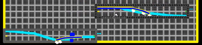
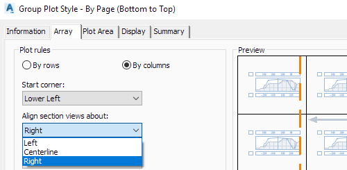
The WisDOT default Section View Group Plot style By Page (Bottom to Top) aligns section views about the centerline. To fit sample lines that combine to exceed the maximum width on a sheet, there is a Section View Group Plot style By Page (Bottom to Top) Right-aligned that will align sections around the right side instead of centerline. This allows any combination of sections that don't exceed maximum sheet width on any single sample line to be on the same section sheet. If the DWG does not have the Section View Group Plot style By Page (Bottom to Top) Right-aligned, the following change can be made to a Section View Group Plot style
Toolspace > Settings > Section View > Group Plot Styles > Right-click By Page (Bottom to Top) > Edit... > Array tab > Align section views about:Right
The section views should be right-aligned only and not left-aligned so that the station labels stay aligned on a sheet.
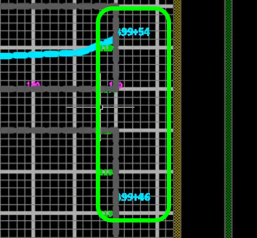
When this change is made, all sections that do not exceed the maximum width on the section sheet will fit. Each section will have it's own offset labels and the centerlines will not line up.