Add section view to existing group
Last updated: 2026-01-06
Total video time: 4:08
Create an individual sample line
-
Ribbon > Home tab > Profile & Section Views panel > Sample Lines
-
Sample Line Tools toolbar > Current sample lines group dropdown
-
Select a Sample Line Group from the list. Make sure to select the correct group before continuing to the next step.
-
-
Sample Line Tools toolbar > Sample line creation methods dropdown > At a Station
-
CREATESAMPLELINES Select an alignment <or press enter key to select from list>:
-
Enter
-
Select an alignment from the list
-
OK
-
-
CREATESAMPLELINES Specify station along baseline:
-
Using the red station selector, select a location for the sample line
-
-
CREATESAMPLELINES enter the left swath width: 75
-
Enter width value
-
Enter
-
-
CREATESAMPLELINES enter the right swath width: 75
-
Enter width value
-
Enter
-
-
-
Esc to exit command
Create individual section view
-
Ribbon > Home tab > Profile & Section Views panel > Section Views dropdown > Create Section View
-
General page
-
Select alignment: 25
-
Sample line group name: SLG-2
-
Sample line: SL-15Will be the highest numbered sample line, but dropdown list will be in station order
-
Section view style: Sheets 1 IN 10 FT Horiz 10 FT Vert
-
Leave the rest defaults
-
Next >
-
-
Offset Range page
-
Automatic: selected
-
Next >
-
-
Elevation Range page
-
Automatic: selected
-
Next >
-
-
Section Display Options page
-
Draw checked for all surfaces
-
Label set: _No Labels for all surfaces
-
Leave the rest defaults
-
Create Section View
-
-
-
CREATESECTIONVIEW Identify section view origin:
-
Choose a location in model space. Crosshair is located at the lower left corner of the section view.
-
Left-click to create the individual section view
-
Add individual section view to an existing sample line group
-
TOOLSPACE > Prospector tab > [current drawing name] > Alignments > Centerline Alignments > 25 > Sample Line Groups > Individual section views Right click > Move to Section View Group...
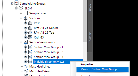
-
Select a Section View Group from the dropdown list
-
OK
-
This will add the individual section view to the section view group in the correct station order.
-
Your section view group may or may not update on its own. If it doesn't, Right click the section view group in the Prospector tab and select Update Section View Layout
Alternate way to create individual sample lines and section views
-
Select an existing sample line
-
Select the diamond grip located on the baseline
-
Specify stretch point or [Base point Copy Undo eXist]
-
Select Copy
-
-
Choose a location along the alignment
-
Left-click to place a copy of the source sample line
-
A sample line is created and added to the sample line group
-
Left-click to continue placing sample lines or press Esc to exit the command
Warning: The copied sample line labels will display correctly. However, the actual station name of copied sample lines must be manually updated in the Section View Group Properties dialog box.
-
Section views are created, but not placed in the correct order on the section sheets. They must be updated manually.
-
Select any section view in the section view group
Warning: WisDOT Section View components do not have grid lines. The visible grid lines are actually associated with the Sheet component. Therefore, when asked to select a section view, an elevation, station, or offset label inside the section view must be selected instead.
-
Ribbon > Section Views contextual tab > Modify View panel > Update Group Layout
-
-
Important notes about adding section views to an existing section view group:
-
Creating additional sample lines and section views may increase the number of sheet layouts needed. New sheet layouts are not automatically generated after creating additional section views. Section views will shift accordingly in model space, but the number of sheets layouts will remain as originally generated. Additional sheet layouts may have to be created.
-
Civil 3D objects and labels inside section views will float with section view placement changes.
-
Any AutoCAD objects (mtext, lines, mleader, etc.) added in model space of a section view that are inside the section view drafting buffer will float with section view placement changes.
-
Any AutoCAD objects (mtext, lines, mleader, etc.) added in a sheet layout (paper space) WILL NOT float with section view placement changes.