Setup-Curb-Prof
Last updated: 2026-01-06
 Description
The assembly includes three slope possibilities derived from LinkWidthandSlope subassemblies. The three slopes represent the maximum (MAX), minimum (MIN), and normal (NORM) cross slopes in the intersections. The default minimum slope is 1%. The default maximum slope is 4%. The default normal slope is 2%. These slopes can be modified to match project-specific requirements. Additional slopes can be added using the LinkWidthandSlope subassembly if desired (superelevation conditions for example). The baseline for this assembly follows the curb return alignment and any profile. The baseline profile is not relevant, so an existing ground profile is typically used. The main road edge of travelway alignment/profile and side road centerline alignment/profile are first targeted as a starting point for the three cross slope possibilities. The subassemblies are named so targeting is easier. This assembly is used to create setup surfaces and profiles to be used as guidelines when developing proposed curb return profiles.
Construction
The assembly includes 7 LinkWidthandSlope subassemblies.

Target ETW Ali_Prof and Sideroad Ali_Prof – This subassembly is used to target both the main road ETW and sideroad centerline alignments and profiles to establish starting points for the slope links. This link is omitted in the assembly.
Max Slope - TARGET Curb Return Ali– This subassembly is used to define the maximum cross slope on the curb region. It is set to target the curb return alignment.
Min Slope– This subassembly is used to define the minimum cross slope on the curb region. Its width is set to parameter reference the width from the Max slope link in the last subassembly. Therefore, no targets are necessary.
Min Slope Extender– This subassembly is used to extend the min slope link out past the curb return alignment by 1' in order to ensure the cross slope is fully extending past the curb return alignment. Tessellation from the corridor frequencies may cause gaps in the data along the curb return alignment. The slope on this link uses the Min Slope subassembly slope as a parameter reference.
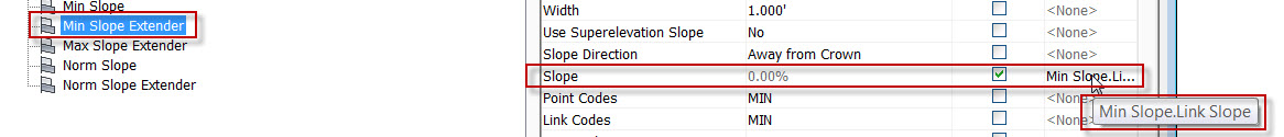
Max Slope Extender– This subassembly is used to extend the max slope link out past the curb return alignment by 1' in order to ensure the cross slope is fully extending past the curb return alignment. Tessellation from the corridor frequencies may cause gaps in the data along the curb return alignment. The slope on this link uses the Max Slope subassembly slope as a parameter reference.

Norm Slope– This subassembly is used to define the minimum cross slope on the curb region. Its width is set to parameter reference the width from the Max slope link in the last subassembly. Therefore, no targets are necessary.

Norm Slope Extender– This subassembly is used to extend the norm slope link out past the curb return alignment by 1' in order to ensure the cross slope is fully extending past the curb return alignment. Tessellation from the corridor frequencies may cause gaps in the data along the curb return alignment. The slope on this link uses the Norm Slope subassembly slope as a parameter reference.


Modeling
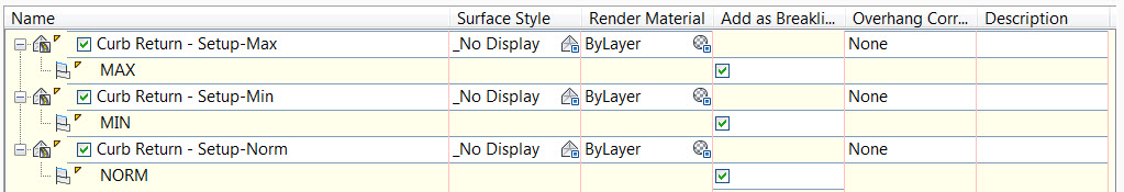
A setup surface will be developed from each of the 3 cross slopes uses the respective MIN, MAX & NORM link codes as breaklines.