SelSubShldMultiPave
Last updated: 2026-01-06
 Description
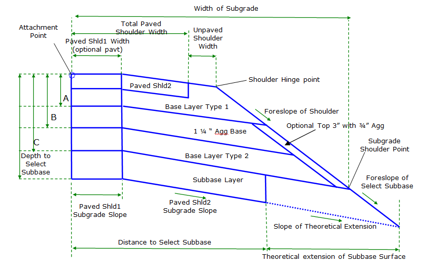
This subassembly inserts a paved shoulder with all pavement, base, and select subbase layers per WisDOT FDM 11-5-15. In addition, Base Course Type 2 material input determines whether the optional 3" of ¾" Aggregate are placed on the foreslope of the shoulder, from the bottom of Base Layer Type 1 to the subgrade shoulder point as shown in WisDOT FDM 14-5-01. This subassembly has an option to create 2 shoulder pavements with independent characteristics.
Behavior
When Create Two Shoulder Pavements is No, Paved Shld1 pavement is not constructed, Paved Shld2 pavement is constructed.
When Create Two Shoulder Pavements is Yes, Paved Shld1 pavement and Paved Shld2 pavement are constructed.
When Create Two Shoulder Pavements is WhenShld1NotEQShld2, the shoulder is constructed as if Create Two Shoulder Pavements is No unless Paved Shld1 slope and Paved Shld2 slope are not equal, in which case the shoulder is constructed as if Create Two Shoulder Pavements is Yes. Paved Shld1 slope and Paved Shld2 slope are determined by logic governing Paved Shld1 SE Method and Paved Shld2 SE Method.
Widths, depths, and aggregate types
The shoulder is inserted using widths and depth parameters provided.
Various base course layer depths can be defined however the Pavement Depth of Adjacent Lane and the Depth to Select Subbase must both be non-zero. The Depth to Select Subbase value defines the depth to the bottom of the lowest base course layer.
All base course depths are measured vertically downward from the Attachment Point. The Depth of Base Layer Type 1 is defined by the Pavement Depth of Adjacent Lane input and this depth cannot be 0. When a Base Depth for 1 ¼" Base is less than the Pavement Depth of Adjacent Lane, then the Base Depth for 1 ¼" Base will be set equal to 0.
When Base Depth for Base Layer Type 2 is less than Base Depth for 1 ¼" Base or less than Pavement Depth of Adjacent Lane, then the Base Depth for Base Layer Type 2 will be set equal to 0. In addition, when Base Depth for Base Layer Type 2 is not 0, the material of this base layer must be specified. If Base Depth for Base Layer Type 2 is not 0 AND the material type of Base Layer Type 2 is set to 3" Aggregate, then a link is inserted parallel to the foreslope of the shoulder link at a distance of 3" below the foreslope link,( i.e. the thickness of aggregate is 3"). This parallel link extends from the bottom of Base Course Layer 1 to the Bottom of Base Course Layer 2. Links defining the bottom of both the 1 ¼" Base Layer and the Base Layer type 2 extend to the intersection of this parallel link. If Base Depth for Base Layer Type 2 is not 0 AND the material type of Base Layer Type 2 is 1 ¼" Agg, then this additional link is not inserted and all base course links extend to the intersection with the shoulder foreslope link. All base course links follow the slope of the Select Subbase Surface, except the optional link that runs parallel to the shoulder foreslope when Base Layer 2 material is 3" Agg. FDM 14-5-01 contains further information about base course material types in WisDOT shoulders.
Methods of determining paved and unpaved shoulder slopes
When a Fixed Slope is used in the Paved Shld2 SE Method and/or UnPaved Shoulder SE Method, the following logic is followed for calculating the slope of the Paved Shld2 and unpaved portions of the shoulder:
-
When Paved Shld2 SE Method and/or UnPaved Shoulder SE Method are set to Fixed Slope, the slopes of the paved and unpaved portion of the shoulder are controlled by the inputs for the Fixed Paved Shld2 Slope and/or Fixed UnPaved Shoulder Slope parameters.
-
If input values for the Fixed Paved Shld2 Slope and/or Fixed UnPaved Shoulder Slope parameters are greater than the "calculated adjacent lane slope" then Fixed Paved Shld2 Slope and/or Fixed UnPaved Shoulder Slope are overridden and the new values are set equal to "calculated adjacent lane slope". Method to Obtain Slope of Adjacent Lane for Rollover Calculation input parameter is used to determine "calculated adjacent lane slope" value. This logic ensures that travel lanes' cross slopes are not steeper than shoulder cross slopes in superelevated sections.
Rollover consideration
When Paved Shld2 SE Method is set to Fixed Slope, the Paved Shld2 slope value can be overridden by Rollover considerations. If the algebraic difference between Fixed Paved Shld2 Slope value and "calculated adjacent lane slope" exceeds the Max Rollover Rate then the Fixed Paved Shld2 Slope value will be overridden and Paved Shld2 slope is calculated so that the algebraic difference between Paved Shld2 slope value and "calculated adjacent lane slope" equals the Max Rollover Rate. Method to Obtain Slope of Adjacent Lane for Rollover Calculation input parameter is used to determine "calculated adjacent lane slope" value. Example #1 rollover exceeded scenario:
- Paved Shld2 SE Method = Fixed Slope
- UnPaved Shoulder SE Method = Match Paved Shoulder Slope
- Fixed Paved Shld2 Slope = -4.0%
- Method to Obtain Slope of Adjacent Lane for Rollover Calculation = Use Outside Lane SE
- Baseline Outside Lane SE = 5.0%
- Max Rollover Rate = 7.0%
In example #1 scenario the Fixed Paved Shld2 Slope value is overridden by Rollover considerations because the algebraic difference between Fixed Paved Shld2 Slope value and "calculated adjacent lane slope" exceeds the Max Rollover Rate. (5% -(-4%)) = 9%; 9% > 7%. A new Paved Shld2 slope will be calculated by the subassembly to be (Calculated Adjacent Lane Slope) – (Max Rollover Rate) = 5% - 7% = -2%. Unpaved shoulder slope will also = -2% because it must match the paved shoulder slope.
When UnPaved Shoulder SE Method is set to Fixed Slope, the Fixed UnPaved Shoulder Slope can be overridden by Rollover considerations. After Paved Shld2 slope value is determined, if the algebraic difference between Paved Shld2 slope value and Fixed UnPaved Shoulder Slope exceeds the Max Rollover Rate then the Fixed UnPaved Shoulder Slope value will be overridden and unpaved shoulder slope value is calculated so that the algebraic difference between Paved Shld2 slope value and unpaved shoulder slope equals the Max Rollover Rate. Example #2 rollover exceeded scenario (integral shoulder pavement):
- Paved Shld2 SE Method = Outside Lane SE
- UnPaved Shoulder SE Method = Fixed Slope
- Baseline Outside Lane SE = 6.0%
- Fixed UnPaved Shoulder Slope = -4.0%
-
Max Rollover Rate = 7.0%
In example #2 scenario the Fixed UnPaved Shoulder Slope value is overridden by Rollover considerations because the algebraic difference between Fixed UnPaved Shoulder Slope value and paved shoulder slope value exceeds the Max Rollover Rate. (6% -(-4%)) = 10%; 10% > 7%. A new unpaved shoulder slope will be calculated by the subassembly to be (paved shoulder slope) – (Max Rollover Rate) = 6% - 7% = -1%.
When Fixed Slope is not used in the Paved Shld2 SE Method and/or UnPaved Shoulder SE Method, the following logic is followed for calculating the slope of the paved and unpaved portions of the shoulder:
- When Paved Shld2 SE Method and/or UnPaved Shoulder SE Method are set toUse Inside Shoulder SE or Use Outside Shoulder SE, the slopes of the Paved Shld2 and unpaved portion of the shoulder are controlled by the shoulder SE rates defined for the baseline alignment. If no shoulder SE rates are defined for the baseline alignment, slopes values are defined by the Fixed Paved Shld2 Slope and Fixed UnPaved Shoulder Slope inputs.
- When Paved Shld2 SE Method and/or UnPaved Shoulder SE Method are set toUse Inside Lane SE or Use Outside Lane SE, the slopes of the paved and unpaved portion of the shoulder are controlled by the lane SE rates defined for the baseline alignment. If no lane SE rates are defined for the baseline alignment, slopes values are defined by the Fixed Paved Shld2 Slope and Fixed UnPaved Shoulder Slope inputs.
-
When Match Paved Shld2 Slope is used for UnPaved Shoulder SE Method the slope of the Unpaved portion of shoulder will always be set equal to the Paved Shld2 Slope (as determined by Paved Shld2 SE Method and accompanying logic).
Select subbase surface slope
The slope of the bottom of the select subbase surface is controlled by the Subgrade Paved Shld2 SE Method parameter. User has the option of entering a fixed slope to be used, following the insertion side Outside Lane SE defined for the baseline alignment, following the insertion side Inside Lane SE defined for the baseline alignment, using the Outside Lane SE defined for the baseline on the opposite side which is then multiplied by -1.0, using the Inside Lane SE defined for the baseline on the opposite side which is then multiplied by -1.0, matching Paved Shld2 slope as determined by Paved Shld2 SE Method, or matching unpaved shoulder slope as determined by UnPaved Shoulder SE Method. When Subgrade Paved Shld2 SE Method is set to Fixed Slope, this slope is obtained from input parameter Fixed Subgrade Slope Paved Shld2 which can be controlled using a Parameter Reference that sets the slope equal to that of the subgrade surface of an adjacent lane. In all situations, the slope of all base course surfaces are parallel the slope of the select subbase surface (subgrade).
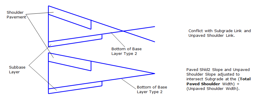
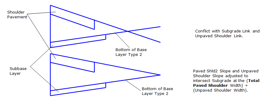
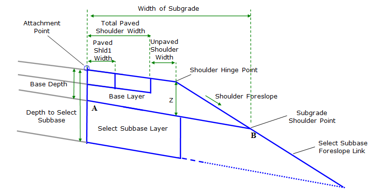
It is possible that the subassembly inputs create a situation in which the bottom of Base Layer Type 2 surface intersects with shoulder top surface prior to the shoulder hinge point, if the shoulder is wide enough. In this case a message will be written to the event viewer, the base course slopes will hold their value, and the Paved Shoulder Slope and UnPaved Shoulder Slope will be adjusted to intersect the subgrade link at the width determined by (Total Paved Shoulder Width) + (Unpaved Shoulder Width). This concept is shown below:
Constant width of subgrade
If Maintain Constant Width is set to ‘False', the Foreslope of Shoulder input will be used to determine shoulder foreslope during superelevated sections and the Width of Subgrade will vary.
If Maintain Constant Width is set to ‘True', then the Width of Subgrade, measured horizontally from the attachment point to the subgrade shoulder point, is computed based on Subgrade Paved Shld2 Slope For Constant Width Calc, Paved Shld2 Slope For Constant Width Calc, UnPaved Shoulder Slope For Constant Width Calc, Total Paved Shoulder Width, Unpaved Shoulder Width, pavement and base layer depths, and Foreslope of Shoulder. The Width of Subgrade is then held constant through superelevated sections, and the Foreslope of the Shoulder parameter is ignored in these sections.
If targets are established for Total Paved Shoulder Width or Unpaved Shoulder Width then the width values retrieved from those targets will be used in the constant Width of Subgrade calculations and the user inputs for Total Paved Shoulder Width and Unpaved Shoulder Width are ignored.
The calculation and corresponding reference diagram used to determine constant Width of Subgrade are shown here:
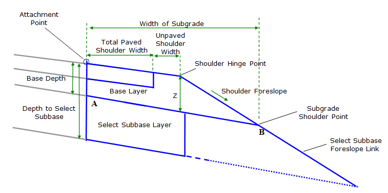
To compute constant width of subgrade
- Total Shoulder Width = (Unpaved Shoulder Width) + (Total Paved Shoulder Width)
- Z Value = (Base Depth) + ((UnPaved Shoulder Width * UnPaved Shoulder Slope For Constant Width Calc) + (Total Paved Shoulder Width * Paved Shld2 Slope For Constant Width Calc) – (Subgrade Paved Shld2 Slope For Constant Width Calc* Total Shoulder Width))
- Width of Subgrade (Width From Point A to Point B) =
- (Total Shoulder Width) + (-1) * ((Z Value) / (Foreslope of Shoulder – Subgrade Paved Shld2 Slope For Constant Width Calc))
-
Base Depth for this subassembly is equal to Pavement Height of Adjacent Lane + Base Depth for 1 ¼" Base + Base Depth for Base Layer Type 2.
Example constant width of subgrade calculation
For the following condtions:
- Total Paved Shoulder Width = 4 ft
- Unpaved Shoulder Width = 6 ft
- Paved Shld2 Slope For Constant Width Calc, = -4%
- UnPaved Shoulder Slope For Constant Width Calc, = -4%
- Subgrade Paved Shld2 Slope For Constant Width Calc = -2%
- Foreslope of Shoulder = 4:1
- Base Depth (bottom of base layer type 2) = 2 ft.
-
No targets set for Total Paved Shoulder Width or Unpaved Shoulder Width.
Z = (2) + (6*(-0.04)) + (4*(-0.04)) – ((-0.02)*10)
= (2) + ((-.24) + (-.16)) – (-.2)
= 2 - .4 + .2
Z = 1.8
Width of Subgrade= (10) + (-1) * (1.8)/((-.25) – (-.02))
= (10) + (-1) * (1.8)/(-.23)
= (10) + (-1)*(-7.826)
Width of Subgrade= 17.826
Select subbase
The Select Subbase Surface is drawn at a width defined by Distance to Select Subbase End. If this parameter is set to 0 ft., the distance used will be equal to (Total Paved Shoulder Width) + (Unpaved Shoulder Width). To close the bottom of the Select Subbase surface, the Slope of the Subbase Closure Link is used to define the slope of the link that extends upward to the intersection with the bottom of the Base Surface.
When Show Select Subbase Foreslope is True, then the select subbase foreslope is drawn, extending from the subgrade shoulder point at a slope defined by the Foreslope of Select Subgrade Portion of Shoulder to the intersection with a temporary projection of the bottom of the Select Subbase surface.
The shoulder is inserted using widths and depth parameters provided. The Total Paved Shoulder Width parameter must be greater than or equal to Paved Shld1 Width value. If the input for Total Paved Shoulder Width is less than the input for Paved Shld1 Width, than the Total Paved Shoulder Width input value will be set equal to the Paved Shld1 Width value.
Various base course layer depths can be defined however the Pavement Depth of Adjacent Lane and the Depth to Select Subbase must both be non-zero. The Depth to Select Subbase value defines the depth to the bottom of the lowest base course layer.
All base course depths are measured vertically downward from the Attachment Point. The Depth of Base Layer Type 1 is defined by the Pavement Depth of Adjacent Lane input and this depth cannot be 0. When a Base Depth for 1 ¼" Base is less than the Pavement Depth of Adjacent Lane, then the Base Depth for 1 ¼" Base will be set equal to 0.
When Base Depth for Base Layer Type 2 is less than Base Depth for 1 ¼" Base or less than Pavement Depth of Adjacent Lane, then the Base Depth for Base Layer Type 2 will be set equal to 0. In addition, when Base Depth for Base Layer Type 2 is not 0, the material of this base layer must be specified. If Base Depth for Base Layer Type 2 is not 0 AND the material type of Base Layer Type 2 is set to 3" Aggregate, then a link is inserted parallel to the foreslope of the shoulder link at a distance of 3" below the foreslope link,( i.e. the thickness of aggregate is 3"). This parallel link extends from the bottom of Base Course Layer 1 to the Bottom of Base Course Layer 2. Links defining the bottom of both the 1 ¼" Base Layer and the Base Layer type 2 extend to the intersection of this parallel link. If Base Depth for Base Layer Type 2 is not 0 AND the material type of Base Layer Type 2 is 1 ¼" Agg, then this additional link is not inserted and all base course links extend to the intersection with the shoulder foreslope link. All base course links follow the slope of the Select Subbase Surface, except the optional link that runs parallel to the shoulder foreslope when Base Layer 2 material is 3" Agg. FDM 14-5-01 contains further information about base course material types in WisDOT shoulders.
Methods of determining paved and unpaved shoulder slopes
When a Fixed Slope is used in the Paved Shld1 SE Method and/or Paved Shld2 SE Method and/or UnPaved Shoulder SE Method, the following logic is followed for calculating the slope of the Paved Shld 1, Paved Shld2, and unpaved portions of the shoulder:
- When Paved Shld1 SE Method and/or Paved Shld2 SE Method and/or UnPaved Shoulder SE Method are set to Fixed Slope, the slopes of the paved and unpaved portion of the shoulder are controlled by the inputs for the Fixed Paved Shld1 Slope and/or Fixed Paved Shld2 Slope and/or Fixed UnPaved Shoulder Slope parameters.
-
If input values for the Fixed Paved Shld1 Slope and/or Fixed Paved Shld2 Slope and/or Fixed UnPaved Shoulder Slope parameters are greater than the "calculated adjacent lane slope" then Fixed Paved Shld1 Slope and/or Fixed Paved Shld2 Slope and/or Fixed UnPaved Shoulder Slope are overridden and the new values are set equal to "calculated adjacent lane slope". Method to Obtain Slope of Adjacent Lane for Rollover Calculation input parameter is used to determine "calculated adjacent lane slope" value. This logic ensures that travel lanes' cross slopes are not steeper than shoulder cross slopes in superelevated sections.
Rollover consideration
When Paved Shld1 SE Method is set to Fixed Slope, the Paved Shld1 slope value can be overridden by Rollover considerations. If the algebraic difference between Fixed Paved Shld1 Slope value and "calculated adjacent lane slope" exceeds the Max Rollover Rate then the Fixed Paved Shld1 Slope value will be overridden and Paved Shld1 slope is calculated so that the algebraic difference between Paved Shld1 slope value and "calculated adjacent lane slope" equals the Max Rollover Rate. Method to Obtain Slope of Adjacent Lane for Rollover Calculation input parameter is used to determine "calculated adjacent lane slope" value. Example #1 rollover exceeded scenario:
- Paved Shld1 SE Method = Fixed Slope
- Paved Shld2 SE Method = Match Paved Shld1 Slope
- UnPaved Shoulder SE Method = Match Paved Shld2 Slope
- Fixed Paved Shld1 Slope = -4.0%
- Method to Obtain Slope of Adjacent Lane for Rollover Calculation = Use Outside Lane SE
- Baseline Outside Lane SE = 5.0%
- Max Rollover Rate = 7.0%
In example #1 scenario the Fixed Paved Shld1 Slope value is overridden by Rollover considerations because the algebraic difference between Fixed Paved Shld1 Slope value and "calculated adjacent lane slope" exceeds the Max Rollover Rate. (5% -(-4%)) = 9%; 9% > 7%. A new Paved Shld1 slope will be calculated by the subassembly to be (Calculated Adjacent Lane Slope) – (Max Rollover Rate) = 5% - 7% = -2%. Unpaved shoulder slope will also = -2% because it must match the paved shoulder slope.
When Paved Shld2 SE Method is set to Fixed Slope, the Paved Shld2 slope value can be overridden by Rollover considerations. After Paved Shld1 slope value is determined, if the algebraic difference between Fixed Paved Shld2 Slope value and Paved Shld1 slope exceeds the Max Rollover Rate then the Fixed Paved Shld2 Slope value will be overridden and Paved Shld2 slope is calculated so that the algebraic difference between Paved Shld2 slope value and Paved Shld1 slope equals the Max Rollover Rate. Paved Shld1 SE Method input parameter is used to determine Paved Shld1 slope value. Example #2 rollover exceeded scenario:
- Paved Shld1 SE Method = Use Outside Lane SE
- Paved Shld2 SE Method = Fixed Slope
- UnPaved Shoulder SE Method = Match Paved Shld2 Slope
- Fixed Paved Shld2 Slope = -4.0%
- Baseline Outside Lane SE = 5.3%
- Max Rollover Rate = 7.0%
In example #2 scenario the Fixed Paved Shld2 Slope value is overridden by Rollover considerations because the algebraic difference between Fixed Paved Shld2 Slope value and Paved Shld1 slope exceeds the Max Rollover Rate. (5.3% -(-4%)) = 9.3%; 9.3% > 7%. A new Paved Shld2 slope will be calculated by the subassembly to be (Paved Shld1 slope) – (Max Rollover Rate) = 5.3% - 7% = -1.7%. Unpaved shoulder slope will also = -1.7% because it must match the Paved Shld2 slope.
When UnPaved Shoulder SE Method is set to Fixed Slope, the Fixed UnPaved Shoulder Slope can be overridden by Rollover considerations. After Paved Shld2 slope value is determined, if the algebraic difference between Paved Shld2 slope value and Fixed UnPaved Shoulder Slope exceeds the Max Rollover Rate then the Fixed UnPaved Shoulder Slope value will be overridden and unpaved shoulder slope value is calculated so that the algebraic difference between Paved Shld2 slope value and unpaved shoulder slope equals the Max Rollover Rate. Example #3 rollover exceeded scenario (integral shoulder pavement):
- Paved Shld2 SE Method = Outside Lane SE
- UnPaved Shoulder SE Method = Fixed Slope
- Baseline Outside Lane SE = 6.0%
- Fixed UnPaved Shoulder Slope = -4.0%
-
Max Rollover Rate = 7.0%
In example #3 scenario the Fixed UnPaved Shoulder Slope value is overridden by Rollover considerations because the algebraic difference between Fixed UnPaved Shoulder Slope value and Paved Shld2 slope value exceeds the Max Rollover Rate. (6% -(-4%)) = 10%; 10% > 7%. A new unpaved shoulder slope will be calculated by the subassembly to be (paved shoulder slope) – (Max Rollover Rate) = 6% - 7% = -1%.
When Fixed Slope is not used in the Paved Shld1 SE Method and/or Paved Shld2 SE Method and/or UnPaved Shoulder SE Method, the following logic is followed for calculating the slope of the paved and unpaved portions of the shoulder:
- When Paved Shld1 SE Method or Paved Shld2 SE Method or UnPaved Shoulder SE Method are set toUse Inside Shoulder SE or Use Outside Shoulder SE, the slopes of thePaved Shld1, Paved Shld2 or unpaved portion of the shoulder are controlled by the shoulder SE rates defined for the baseline alignment. If no shoulder SE rates are defined for the baseline alignment, slopes values are defined by the Fixed Paved Shld1 Slope, Fixed Paved Shld2 Slope or Fixed UnPaved Shoulder Slope inputs.
- When Paved Shld1 SE Method or Paved Shld2 SE Method or UnPaved Shoulder SE Method are set toUse Inside Lane SE or Use Outside Lane SE, the slopes of the Paved Shld1, Paved Shld2 or unpaved portion of the shoulder are controlled by the lane SE rates defined for the baseline alignment. If no lane SE rates are defined for the baseline alignment, slopes values are defined by the Fixed Paved Shld1 Slope, Fixed Paved Shld2 Slope or Fixed UnPaved Shoulder Slope inputs.
-
When Match Paved Shld1 Slope is used for Paved Shld2 SE Method the slope of the Paved Shld2 portion of shoulder will always be set equal to the Paved Shld1 Slope (as determined by Paved Shld1 SE Method and accompanying logic). When Match Paved Shld2 Slope is used for UnPaved Shoulder SE Method the slope of the Unpaved portion of shoulder will always be set equal to the Paved Shld2 Slope (as determined by Paved Shld2 SE Method and accompanying logic).
Select subbase surface slope
The slope of the bottom of the select subbase surface is controlled by the Subgrade Paved Shld1 SE Method parameter between the attachment point to a distance defined by Paved Shld1 Width. The slope of the bottom of the select subbase surface is controlled by the Subgrade Paved Shld2 SE Method parameter between from the end of Paved Shld1 pavement to the subgrade shoulder point. User has the option of entering a fixed slope to be used, following the insertion side Outside Lane SE defined for the baseline alignment, following the insertion side Inside Lane SE defined for the baseline alignment, using the Outside Lane SE defined for the baseline on the opposite side which is then multiplied by -1.0, using the Inside Lane SE defined for the baseline on the opposite side which is then multiplied by -1.0, matching Paved Shld1 slope as determined by Paved Shld1 SE Method matching Paved Shld2 slope as determined by Paved Shld2 SE Method, or matching unpaved shoulder slope as determined by UnPaved Shoulder SE Method. When Subgrade Paved Shld1SE Method or Subgrade Paved Shld2 SE Method is set to Fixed Slope, this slope is obtained from input parameter Fixed Subgrade Slope Paved Shld1 or Fixed Subgrade Slope Paved Shld2 which can be controlled using a Parameter Reference that sets the slope equal to that of the subgrade surface of an adjacent lane. In all situations, the slope of all base course surfaces are parallel to the slope of the select subbase surface (subgrade) for the appropriate Paved Shld1 or Paved Shld2 area.
It is possible that the subassembly inputs create a situation in which the bottom of Base Layer Type 2 surface intersects with shoulder top surface prior to the shoulder hinge point, if the shoulder is wide enough. In this case a message will be written to the event viewer, the base course slopes will hold their value, and the Paved Shoulder Slope and UnPaved Shoulder Slope will be adjusted to intersect the subgrade link at the width determined by (Total Paved Shoulder Width) + (Unpaved Shoulder Width). This concept is shown below:
Constant width of subgrade
If Maintain Constant Width is set to ‘False', the Foreslope of Shoulder input will be used to determine shoulder foreslope during superelevated sections and the Width of Subgrade will vary.
If Maintain Constant Width is set to ‘True', then the Width of Subgrade, measured horizontally from the attachment point to the subgrade shoulder point, is computed based on Subgrade Paved Shld1 Slope For Constant Width Calc, Subgrade Paved Shld2 Slope For Constant Width Calc, Paved Shld1 Slope For Constant Width Calc, Paved Shld2 Slope For Constant Width Calc, UnPaved Shoulder Slope For Constant Width Calc, Total Paved Shoulder Width, Unpaved Shoulder Width, pavement and base layer depths, and Foreslope of Shoulder. The Width of Subgrade is then held constant through superelevated sections, and the Foreslope of the Shoulder parameter is ignored in these sections.
If targets are established for Paved Shld1 Width, Total Paved Shoulder Width or Unpaved Shoulder Width then the width values retrieved from those targets will be used in the constant Width of Subgrade calculations and the user inputs for Total Paved Shoulder Width and Unpaved Shoulder Width are ignored.
The calculation and corresponding reference diagram used to determine constant Width of Subgrade are shown here:
To compute constant width of subgrade
- Total Shoulder Width = (Unpaved Shoulder Width) + (Total Paved Shoulder Width)
- Z Value = (Base Depth) + [(UnPaved Shoulder Width * UnPaved Shoulder Slope For Constant Width Calc) + ((Total Paved Shoulder Width- Paved Shld1 Width) * Paved Shld2 Slope For Constant Width Calc) + (Paved Shld1 Width * Paved Shld1 Slope For Constant Width Calc) – (Subgrade Paved Shld1 Slope For Constant Width Calc * Paved Shld1 Width) - (Subgrade Paved Shld2 Slope For Constant Width Calc * (Unpaved Shoulder Width + Total Paved Shoulder Width - Paved Shld1 Width))]
- Width of Subgrade (Width From Point A to Point B) =
- (Total Shoulder Width) + (-1) * ((Z Value) / (Foreslope of Shoulder – Subgrade Paved Shld2 Slope For Constant Width Calc))
-
Base Depth for this subassembly is equal to Pavement Height of Adjacent Lane + Base Depth for 1 ¼" Base + Base Depth for Base Layer Type 2.
Example constant width of subgrade calculation
For the following condtions:
- Paved Shld1 Width = 2 ft
- Total Paved Shoulder Width = 8 ft
- Unpaved Shoulder Width = 2 ft
- Paved Shld1 Slope For Constant Width Calc, = -4%
- Paved Shld2 Slope For Constant Width Calc, = -4%
- UnPaved Shoulder Slope For Constant Width Calc, = -4%
- Subgrade Paved Shld1 Slope For Constant Width Calc = -2%
- Subgrade Paved Shld2 Slope For Constant Width Calc = -2%
- Foreslope of Shoulder = 4:1
- Base Depth (bottom of base layer type 2) = 2 ft.
-
No targets set for Paved Shld1 Width,Total Paved Shoulder Width or Unpaved Shoulder Width.
Z = (2) + [(2*(-0.04)) + ((8-2)*(-0.04)) + (2*(-0.04)) – ((-0.02)*2) - ((-0.02) * (2+8-2))
= (2) + [(-0.08) + (-0.24) + (-0.08) - (-0.04) - (-0.16)]
= (2) + [(-.4) - (-.2)]
= 2 - .4 + .2
Z = 1.8
Width of Subgrade= (10) + (-1) * (1.8)/((-.25) – (-.02))
= (10) + (-1) * (1.8)/(-.23)
= (10) + (-1)*(-7.826)
Width of Subgrade= 17.826
Select subbase
The Select Subbase Surface is drawn at a width defined by Distance to Select Subbase End. If this parameter is set to 0 ft., the distance used will be equal to (Total Paved Shoulder Width) + (Unpaved Shoulder Width). To close the bottom of the Select Subbase surface, the Slope of the Subbase Closure Link is used to define the slope of the link that extends upward to the intersection with the bottom of the Base Surface.
When Show Select Subbase Foreslope is True, then the select subbase foreslope is drawn, extending from the subgrade shoulder point at a slope defined by the Foreslope of Select Subgrade Portion of Shoulder to the intersection with a temporary projection of the bottom of the Select Subbase surface.
Attachment & layout mode operation
The attachment point is at the inside edge of the paved shoulder, which is typically at the outside edge of the traveled way.
In layout mode, this subassembly displays the links comprising the shoulder for a normal crown roadway situation, using default top shoulder slopes and select subbase surface slopes. If Create Two Shoulder Pavements is No, Paved Shld1 pavement is not drawn in Layout Mode. If Create Two Shoulder Pavements is Yes or Only When Paved Shld1 Slope Is Not Equal To Paved Shld2 Slope, Paved Shld1 pavement is drawn.
Input parameters
Info: All dimensions are in feet unless otherwise noted. All slopes are in run-over-rise form (for example, 4:1) unless indicated as a percent slope with a "%" sign.
| Parameter | Description | Type | Default |
|---|---|---|---|
| Side | Specifies which side to place the subassembly. | Left/Right | Right |
| Maintain Constant Width | Specifies whether the foreslope will vary to maintain a constant Width of Subgrade. If set to No, the Width of Subgrade will vary and the foreslope slope is maintained; foreslope slope value is determined by user input in the Foreslope of Shoulder input parameter. If set to Yes the Width of Subgrade value is maintained and the foreslope slope will vary; method for calculating Width of Subgrade is described in the Behavior Section. | Yes/No | Yes |
| Create Two Shoulder Pavements | Specifies whether one or two shoulder pavements are constructed. If set to Yes, both Paved Shld1 and Paved Shld2 pavements are constructed. If set to No, only Paved Shld2 pavement is constructed. When set to WhenShld1NotEQShld2, if slope of Paved Shld1 (as determined by Paved Shld1 SE Method) is not equal to (<>) Paved Shld2 slope (as determined by Paved Shld2 SE Method) then subassembly will behave as if Create Two Shoulder Pavements is Yes. When set to WhenShld1NotEQShld2, if slope of Paved Shld1 (as determined by Paved Shld1 SE Method) is equal to (=) Paved Shld2 slope (as determined by Paved Shld2 SE Method) then subassembly will behave as if Create Two Shoulder Pavements is No. |
List of options: a.) Yes, b.) No, c.) WhenShld1NotEQShld2 |
No |
| Paved Shld1 Pavement Height | Depth of Paved Shld1 pavement measured from the attachment point down. | Numeric, Positive | 0.333 feet |
| Paved Shld2 Pavement Height | Depth of Paved Shld2 pavement measured from end of Paved Shld1 pavement down, or measured from attachment point down if Paved Shld1 pavement is not constructed. | Numeric, Positive | 0.333 feet |
| Pavement Depth of Adjacent Lane | Depth of the pavement on the lane adjacent to shoulder. This depth defines the depth to the bottom of Base Layer Type 1. Value cannot be 0. Value can be set with a parameter reference. | Numeric, Positive, non-zero | 0.5 feet |
| Base Depth for 1 ¼" Base | Distance to the bottom of the 1 ¼" Aggregate base course layer, shown as dimension B in the diagram. This distance is measured down from the attachment point. If this parameter is equal to the Depth to Select Subbase parameter, no Base Type 2 Layer or Subbase Layer will be included. If there is no 1 ¼" base course layer, a zero depth should be specified. Value can be set with a Parameter Reference. | Numeric, Positive | 0 ft. |
| Base Depth for Base Layer Type 2 | Distance to the bottom of the Base Type 2 base course layer, shown as Dimension C in the diagram. This distance is measured down from the attachment point. If this parameter is equal to the Depth to Select Subbase parameter, no Subbase Layer will be included. If there is no Base Layer Type 2 base course layer, a zero depth should be specified. Value can be set with a parameter reference. | Numeric, Positive | 0 ft. |
| Base Course Type 2 Material | Type of material to use in the Base Type 2 Layer. If the material specified here is 3" Agg (Agg300inch), then the top 3" of base course on the foreslope, from the bottom of Base Layer Type 1 to the subgrade shoulder point, will contain ¾" Aggregate. If 1 ¼" Agg (Agg125inch) is selected, then base course layers extend all the way to the intersection with the foreslope link. |
List of options: a.) Agg125inch, b.) Agg300inch |
Agg125inch |
| Depth to Select Subbase | Distance to the top of the Subgrade Surface, also the bottom of the Select Subbase. This measurement is taken from the top of the pavement. A zero depth is not allowed. | Numeric, Positive, non-zero | 2.0 ft. |
| Paved Shld1 Width | Width of the first paved portion of the shoulder. | Numeric, non-negative | 8.0 ft. |
| Total Paved Shoulder Width | Width to outside edge of the Paved Shld2 pavement, measured from the attachment point. | Numeric, non-negative | 12.0 ft. |
| Unpaved Shoulder Width | Width of the unpaved portion of the shoulder from the end of Paved Shld2 pavement to the shoulder hinge point. | Numeric, non-negative | 2 ft. |
| Paved Shld1 SE Method | Specifies whether the top surface of the Paved Shld1 pavement should use SE rates defined for the baseline alignment if it exists, or a Fixed Value. |
List of options: a.)FixedSlope, b.) OutsideLane c.) InsideLane d.) OutsideShoulder e.) InsideShoulder |
InsideLane |
| Paved Shld2 SE Method | Specifies whether the top surface of the Paved Shld2 pavement should use SE rates defined for the baseline alignment if it exists, or a Fixed Value. If MatchPavedShld1Slope is used, all other considerations are ignored and the slope of the Paved Shld2 pavement surface will equal the slope of Paved Shld1 as determined by Paved Shld1 SE Method |
List of options: a.) FixedSlope, b.) OutsideLane c.) InsideLane d.) OutsideShoulder e.) InsideShoulder f.) MatchPaved-Shld1Slope |
Outside-Shoulder |
| UnPaved Shoulder SE Method | Specifies whether the top surface of the unpaved shoulder should use SE rates defined for the baseline alignment if it exists, or a Fixed Value. If Match Paved Shld2 Slope is used, all other considerations are ignored and the slope of the UnPaved top surface of the shoulder will equal the slope of Paved Shld2 as determined by Paved Shld2 SE Method |
List of options: a.) FixedSlope, b.) OutsideLane c.) InsideLane d.) OutsideShoulder e.) InsideShoulder, f.) MatchPavedShld2Slope |
MatchPaved-Shoulder2Slope |
| Fixed Paved Shld1 Slope | Cross slope of the Paved Shld1 pavement. This value is used if Paved Shld1 SE Method is set to Fixed Slope, or if superelevation is not defined for the baseline alignment. Value can be set using a parameter reference. | Slope | -4.0% |
| Fixed Paved Shld2 Slope | Cross slope of the Paved Shld2 pavement. This value is used in if Paved Shld2 SE Method is set to Fixed Slope, or if superelevation is not defined for the baseline alignment. Value can be set using a parameter reference | Slope | -4.0% |
| Fixed UnPaved Shoulder Slope | Cross slope of the UnPaved shoulder surface. This value is used in if UnPaved Shoulder SE Method is set to Fixed Slope, or if superelevation is not defined for the baseline alignment. Value can be set using a parameter reference. | Slope | -4.0% |
| Foreslope of Shoulder | Slope of the Foreslope of the shoulder which extends from the Shoulder Hinge Point to the Subgrade Shoulder Point. If Maintain Constant Width set to ‘False', the Foreslope specified here is maintained in superelevated sections. If Maintain Constant Width is set "True" then this value will be used to calculate the Width of Subgrade value but it will not be the foreslope slope in superelevated sections. | Slope, Positive | 4:1 |
| Foreslope of Select Subbase Portion of Shoulder | Slope of link inserted after the foreslope link. To compute the end point of this link, the subbase surface is theoretically extended to the intersection with this foreslope link. No links are inserted as part of the subbase surface projection. | Slope, Positive | 4:1 |
| Show Select Subbase Foreslope | The insertion of the select subbase foreslope link, which is the foreslope link inserted after the Subgrade Shoulder Point, can be avoided by setting this parameter to No. | Yes/No | No |
| Distance to Select Subbase End | Defines the distance to the end of the select subbase surface, measured horizontally from the attachment point. If a value of 0 is entered, the distance will be set equal to (Paved Shld2 Width) + (Unpaved Shoulder Width) | Numeric, Positive | 14 ft |
| Slope of Subbase Closure Link | Slope of link that extends upward from the end point of the bottom of the Select Subbase surface to the intersection with the bottom of the Base link. | Slope, Positive | 0.001:1 |
| Subgrade Paved Shld1 SE Method | Specifies the method used to determine the slope of the bottom of the select subbase surface under Paved Shld1 portion of the shoulder, identified as being between the attachment point and the end of Paved Shld1 pavement. Use the Opposite Side SE Multiplied by -1.0, results in the bottom of the select subbase surface slope being equal to Superelevation Slope defined for the baseline on the side opposite the insertion side, multiplied by -1.0. If PavedShld1, PavedShld2, or UnPavedShoulder is selected, the Subgrade will be parallel to the top of shoulder surface as determined by Paved Shld1 SE Method, Paved Shld2 SE Method or UnPaved Shoulder SE Method. |
String, Combo List of options: a.) OutsideLane, b.) InsideLane, c.) InvOppOutsideLane, d.) InvOppInsideLane, e.) FixedSlope, f.) PavedShld1, g.) PavedShld2, h.) UnPavedShoulder |
OutsideLane |
| Subgrade Paved Shld2 SE Method | Specifies the method used to determine the slope of the bottom of the select subbase surface under Paved Shld2, identified as being between the end of Paved Shld1 pavement and the subgrade shoulder point . Use the Opposite Side SE Multiplied by -1.0, results in the bottom of the select subbase surface slope being equal to Superelevation Slope defined for the baseline on the side opposite the insertion side, multiplied by -1.0. If PavedShld1, PavedShld2, or UnPavedShoulder is selected, the Subgrade will be parallel to the top of shoulder surface as determined by Paved Shld1 SE Method, Paved Shld2 SE Method or UnPaved Shoulder SE Method. |
String, Combo List of options: a.) OutsideLane, b.) InsideLane, c.) InvOppOutsideLane, d.) InvOppInsideLane, e.) FixedSlope, f.) PavedShld1, g.) PavedShld2, h.) UnPavedShoulder |
OutsideLane |
| Fixed Subgrade Slope Paved Shld1 | Fixed cross slope of the bottom of the select subbase surface under Paved Shld1. This value is used if FixedSlope is selected as the Subgrade Paved Shld1 SE Method or superelevation is not specified for the baseline alignment. | Slope | -2% |
| Fixed Subgrade Slope Paved Shld2 | Fixed cross slope of the bottom of the select subbase surface under Paved Shld2. This value is used if FixedSlope is selected as the Subgrade Paved Shld2 SE Method or superelevation is not specified for the baseline alignment. | Slope | -2% |
| Max Rollover Rate | Value is used to limit the maximum algebraic difference between the slope of the adjacent lane and the Paved Shld1 slope, the adjacent lane and the Paved Shld2 slopes, the Paved Shld1 and Paved Shld2 slopes, and the Paved Shld2 and Unpaved Shoulder slopes. Rollover based shoulder rotation in superelevated sections is described in the Behavior section. | Slope | 7% |
| Method to Obtain Slope of Adjacent Lane | Specifies the method to use to determine the slope of the adjacent lane. When using Outside or Inside Lane SE of the insertion side, or the opposite side SE multiplied by -1.0, the SE rate that is used is that which is defined for the baseline. Fixed Slope will automatically be used when no baseline SE is defined. |
String, Combo List of options: a.) OutsideLane, b.) InsideLane, c.) InvOppOutsideLane, d.) InvOppInsideLane, e.) FixedSlope |
FixedSlope |
| Fixed Slope of Adjacent Lane for Rollover Calculation | Slope value to be used when calculating rollover and Method to Obtain Slope of Adjacent Lane is set to FixedSlope. Value can (and should) be set by a parameter reference. | Slope | -2% |
| Subgrade Paved Shld1 Slope For Constant Width Calc | Slope value of the Subgrade Paved Shld1 surface during Normal Crown situations. This value is used for the sole purpose of computing a constant subgrade width value, it has no effect on the actual subgrade surface slope. | Slope | -2% |
| Subgrade Paved Shld2 Slope For Constant Width Calc | Slope value of the Subgrade Paved Shld2 surface during Normal Crown situations. This value is used for the sole purpose of computing a constant subgrade width value, it has no effect on the actual subgrade surface slope. | Slope | -2% |
| Paved Shld1 Slope For Constant Width Calc | Slope value of the Paved Shld1 Shoulder surface during Normal Crown situations. This value is used for the sole purpose of computing a constant subgrade width value, it has no effect on the actual Paved Shoulder surface slope. | Slope | -4% |
| Paved Shld2 Slope For Constant Width Calc | Slope value of the Paved Shld2 Shoulder surface during Normal Crown situations. This value is used for the sole purpose of computing a constant subgrade width value, it has no effect on the actual Paved Shoulder surface slope. | Slope | -4% |
| UnPaved Shoulder Slope For Constant Width Calc | Slope value of the UnPaved Shoulder surface during Normal Crown situations. This value is used for the sole purpose of computing a constant subgrade width value, it has no effect on the actual UnPaved Shoulder surface slope. | Slope | -4% |
| Additional Link Codes For L1 | Link codes added to L1 in addition to Top, and PaveShld1. See the subassembly coding diagram at the end of this document for L1 location | Comma-separated string | None |
| Additional Link Codes For L5 | Link codes added to L5 in addition to Top, and PaveShld1. See the subassembly coding diagram at the end of this document for L5 location | Comma-separated string | None |
| Additional Link Codes For L6 | Link codes added to L6 in addition to Top, and PaveShld1. See the subassembly coding diagram at the end of this document for L6 location | Comma-separated string | None |
| Additional Link Codes For L17 | Link codes added to L17 in addition to Top, and PaveShld1. See the subassembly coding diagram at the end of this document for L17 location | Comma-separated string | None |
Target parameters
This section lists the parameters in this subassembly that can be mapped to one or more target objects, such as a surface, alignment, or profile object in a drawing.
| Parameter | Description | Status |
|---|---|---|
| Paved Shld1 Width | Object that defines the horizontal location of the edge of the Paved Shld1 portion of the shoulder. The following object types can be used as targets for specifying the width: alignments, polylines, feature lines, or survey features. | Optional |
| Total Paved ShoulderWidth | Object that defines the horizontal location of the edge of the Paved Shld2 portion of the shoulder. The following object types can be used as targets for specifying the width: alignments, polylines, feature lines, or survey features. | Optional |
| Unpaved Shoulder Width | Object that defines the horizontal location of the shoulder hinge point. The following object types can be used as targets for specifying the width: alignments, polylines, feature lines, or survey features. | Optional |
| Distance to Select Subgrade End | Object that defines the horizontal location of the end of the select subgrade surface. The following object types can be used as targets for specifying the width: alignments, polylines, feature lines, or survey features. | Optional |
Output parameters
| Parameter | Description | Type |
|---|---|---|
| Shoulder Foreslope | Slope of the link from the hinge point to the subgrade shoulder point. | Slope |
| Paved Shld1 Slope | Slope of the Paved Shld1 pavement | Slope |
| Paved Shld2 Slope | Slope of the Paved Shld2 pavement | Slope |
| Unpaved Shoulder Slope | Slope of the unpaved surface between Paved Shld2 pavement and the hinge point | Slope |
Coding diagram
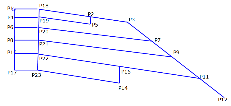
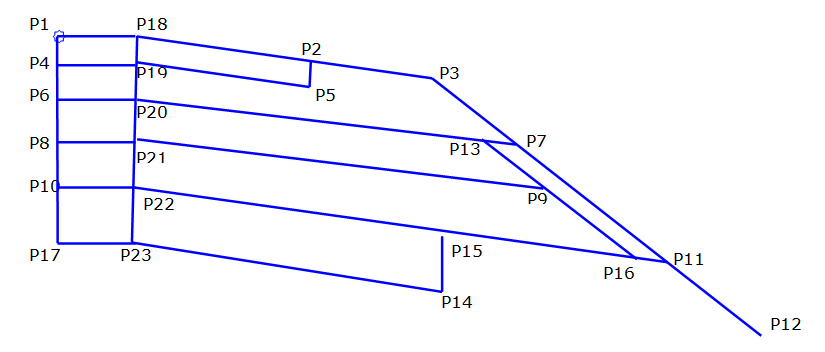
Points Coding diagram
When Base Layer Type 2 = 1 ¼" Agg
Points Coding diagram
When Base Layer Type 2 = 3" Agg
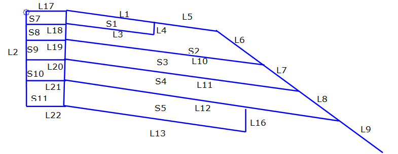
Link and Shapes Coding diagram
When Base Layer Type 2 = 1 ¼" Agg
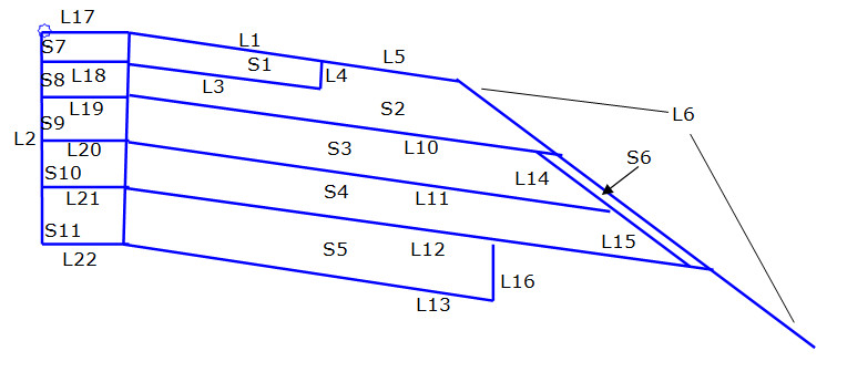
Link and Shapes Coding diagram
When Base Layer Type 2 = 3" Agg
Point, Link, and Shape codes
| Point/Link/Shape | Codes | Description |
|---|---|---|
| P2 | EPS2 | Edge of Paved Shld2, finish grade |
| P3 | ES_Unpaved | Edge of gravel Shoulder; outer edge of unpaved portions of shoulder on finished grade. |
| P4 | EPS1_Pave1_In | Inside Edge of Paved Shld1, bottom of pavement |
| P5 | EPS2_Pave1 | Edge of Paved Shld2, bottom of pavement |
| P6 | EPS1_Base1_In | Inside Edge of Paved Shld1 on the Base1 Layer |
| P7 | ES_Base1 | Edge of shoulder on Base1 Layer |
| P8 | EPS1_Base2_In | Inside Edge of Paved Shld1 on the Base2 layer |
| P9 | ES_Base2 | Edge of shoulder on Base2 Layer |
| P10 | EPS1_Selsub_In | Inside Edge of Paved Shld1 on the subbase layer |
| P11 | SGSP | Subgrade Shoulder |
| P12 | SGSP2 | Foreslope extension point |
| P14 | Daylight_Sub | |
| P15 | SUBG_Int | |
| P16 | ES_Selsub | Edge of paved shoulder on Base2 Layer |
| P17 | EPS1_Sub_In | Edge of Paved Shld1 pavement, finish grade |
| P18 | EPS1 | Outside Edge of Paved Shld1, bottom of pavement |
| P19 | EPS1_Pave1 | Outside Edge of Paved Shld1 on the Base1 Layer |
| P20 | EPS1_Base1 | Outside Edge of Paved Shld1 on the Base2 layer |
| P21 | EPS1_Base2 | Outside Edge of Paved Shld1 on the subbase layer |
| P22 | EPS1_Selsub | Outside Edge of Paved Shld1 on the subgrade layer |
| P23 | EPS1_Sub | Finish grade of the shoulder |
| L1 |
Top PaveShld2 |
|
| L3 | Base | |
| L4 | Base | Top of the first base layer; surface always exists |
| L5 |
Top Base |
|
| L6 |
Top Base |
Top of the 1 ¼" base course layer. |
| L7 |
Top Base1 |
Top of the Base Type 2 Layer; this is an optional layer |
| L8 |
Top Base2 |
Top of the Subbase Layer; this is an optional layer |
| L9 | Top | |
| L10 | Base1 | |
| L11 | Base2 | |
| L12 | Selsub | Top of the Subgrade or Datum |
| L13 |
FINGRND SUBG |
|
| L14 | Base1 | |
| L15 | Base2 | |
| L16 |
FINGRND SUBG |
Finish grade of the shoulder |
| L17 |
Top PaveShld1 |
|
| L18 | Base | |
| L19 | Base1 | |
| L20 | Base2 | |
| L21 | Selsub | |
| L22 |
FINGRND SUBG |
|
| S1 | Pave2_Shld | |
| S2 | Base | |
| S3 | Base1 | |
| S4 | Base2 | |
| S5 | Select_Subbase | |
| S6 | Base | |
| S7 | Pave1_Shld | |
| S8 | Base | |
| S9 | Base1 | |
| S10 | Base2 | |
| S11 | Select_Subbase |