GenCF
Last updated: 2026-01-06
 Description
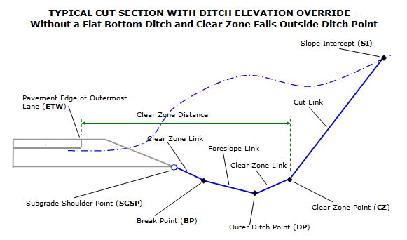
This subassembly closes the sections from the outside edge of the roadway (subgrade shoulder point) to cut or fill slope intersect point.
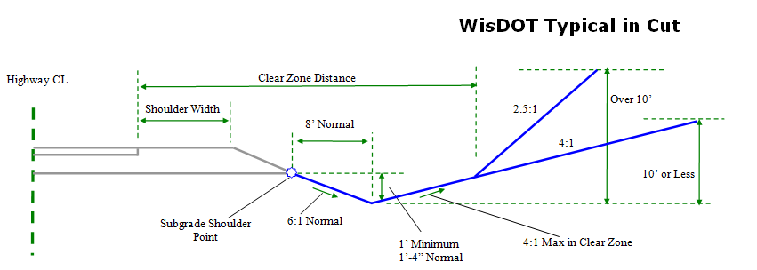
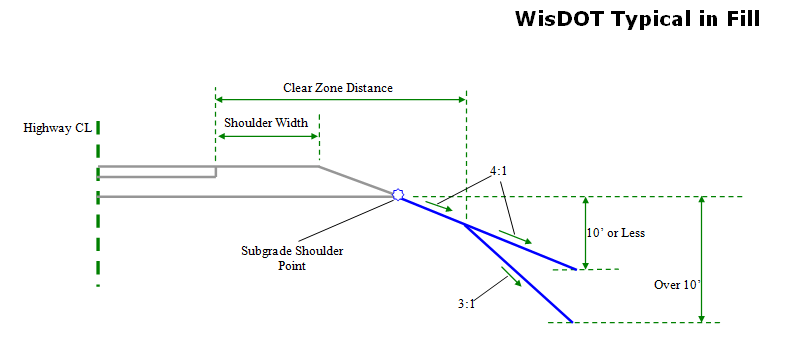
Subassembly provides a variety of solutions for cut and fill conditions as described below. Parameters to complete a cut or fill section include insuring that a safe clear zone distance and slope are provided, in addition to providing parameters for both a v-ditch or a flat bottom ditch in cut sections.
When building cut sections, a minimum ditch depth can be specified to follow WisDOT standards which require a minimum 1 foot ditch from the slope intercept point to the bottom of the ditch.
The final cut or fill link can be allowed to follow WisDOT standards for steep and flat rates based on a maximum height specified, or the user can override this standard with a distance, offset or slope that controls the final link.
Behavior
This subassembly is designed to accommodate a wide variety of clear zone, cut section and fill section configurations.It has the option of allowing you to specify an elevation for the ditch point and varies in its behavior depending on whether a ditch elevation is assigned.
Fill section
If a fill condition is determined, the logical steps used are as follows:
- The distance between the subgrade shoulder point and the daylight surface is determined. If the distance is less than or equal to the Minimum Fill Height value, then section may be treated as being in a cut condition if Optional Ditch in Small Fill Situations parameter is set to True. The locations where Minimum Fill Height requirements are not met are written out to the Event Viewer.
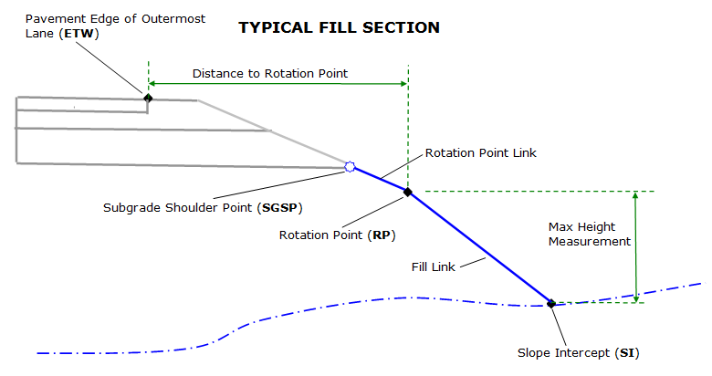
- The Distance to Rotation Point and Fill Slope to Rotation Point are used to temporarily construct the first fill link, hereby called the rotation point link ending at a test point. The Distance to Rotation Point in most cases is measured from the edge of the topmost pavement layer of the outermost lane (ETW).The offset of this point is the Offset To Measure Distance To Rotation Point From and can be input by the user or passed from the LnGeneric subassembly by using a Parameter Reference. If the test point falls above the daylight surface, the first rotation point link is inserted. If the test point falls below the daylight surface, the rotation point link will end at its intersection with the daylight surface, thereby completing the fill section. This point then becomes the slope intercept point, not the rotation point.
- To close to the daylight surface in fill:
- If Override Backslope of Final Link Intersecting Daylight Surface Type is set to No, the intercept to the daylight surface is calculated using the Flat Rate of Fill Slope value.
- If the height of the flat fill slope exceeds the Max Height, the intercept to the daylight surface is re-calculated using the Steep Rate of Fill Slope value.
If Override Backslope of Final Link Intersecting Daylight Surface Type is set to anything other than No, then the Final Link is defined using the parameter set in Override Backslope of Final Link Intersecting Daylight Surface Value1 or Value2 (depending on the Type), rather than the Flat and Steep Rate of Fill Slope.
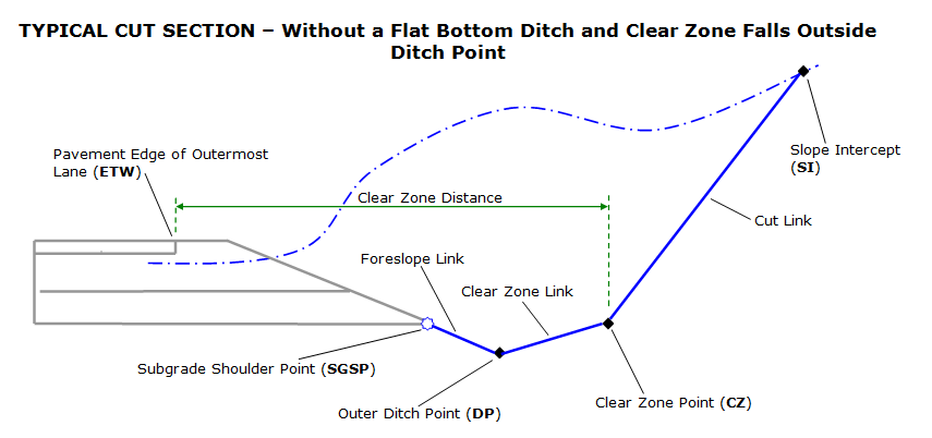
Cut section
If a cut condition is determined, the logical steps used are as follows:
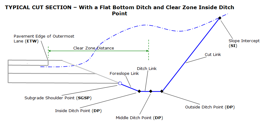
- The Foreslope Slope and Foreslope Width are used to construct the first cut link, hereby called the foreslope link, ending at a test point.If the distance between the test point and the daylight surface (measured vertically) is less than the Ditch Depth in Small Fill parameter, then the foreslope link is extended until this Ditch Depth is attained, but the test point would stop at a horizontal distance of 20 feet if it cannot find the desired depth so far(in case the surface is very flat).The end point of the foreslope link is the Inside Ditch Point (DP)
- Ditch Link is inserted using Bottom Width parameter.
- The Clear Zone Distance is used to determine if a clear zone link is inserted.In most cases, the Clear Zone Distance is measured from the edge of the topmost pavement layer of the outermost lane (ETW Offset).The offset of this point can be input by the user or passed from the LnGeneric subassembly using a Parameter Reference.If the Clear Zone Distance defined falls outside the Outer Ditch Point, a temporary link is constructed from the Outer Ditch Point using the distance required to attain the Clear Zone Distance and the Clear Zone Slope, ending in a test point.If the test point falls above the daylight surface, then the clear zone link will end at its intersection with the daylight surface, thereby completing the cut section.This point then becomes the slope intercept point, not the clear zone point.If the test point falls below the daylight surface, the clear zone link is inserted.
- To close to the daylight surface in cut:
- If Override Backslope of Final Link Intersecting Daylight Surface Type is set to No, the intercept to the daylight surface is calculated using the Flat Rate of Cut Slope value.
- If the height of the flat cut slope exceeds the Max Height, the intercept to the daylight surface is re-calculated using the Steep Rate of Cut Slope value.
If Override Backslope of Final Link Intersecting Daylight Surface Type is set to anything other than No, then the Final Link is defined using the parameter set in Override Backslope of Final Link Intersecting Daylight Surface Value1 or Value 2 (depending on the type set), rather than the Flat and Steep Rate of Cut Slope.
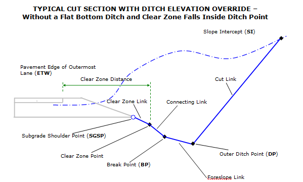
When Override Ditch Bottom Elevation is set to Anything other than No
In cut sections, situations exist where the location of the subgrade shoulder point and the elevation of the ditch bottom are the only knowns, along with some slope parameters.When the Override Ditch Bottom Elevation is set to a value other then No it is assumed you are working in a cut section and that the elevation of the bottom of the ditch is known and not calculated using slope and width parameters.The Override Ditch Bottom Elevation allows the following overriding parameters:
- Elevation. When the override is set to Elevation, the Ditch Bottom Elevation parameter is used to set the elevation of the bottom of the ditch.
-
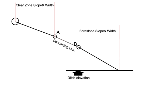
Profile.When the override is set to Profile, the elevation of the ditch bottom is retrieved from a target profile.If no elevation can be retrieved from the target profile specified, subassembly functions in the same way it would if Override Ditch Bottom Elevation was set to No.If the elevation retrieved is too high, (in the following figure, ditch elevation is higher than point A's elevation), this SA functions in the same say it would if Override Ditch Bottom Elevation is set to No and a message is sent to the event viewer.
When an override is used, the subassembly follows the following logic:
- Establish the elevation of the ditch point.
-
From the Ditch Point(DP) elevation established, go up using the Foreslope Width and Foreslope Slopespecified to a test point called B, (Actually this point's offset is not decided yet).A clear zone link is inserted using theClear Zone Slope and Clear Zone Distance entered from the subgrade shoulder point down to a point called A.If point A lies above point B, the clear zone link and the foreslope link are connected together by a link referred to as the Connecting Link, using the slope entered by user in the Connecting Link Slope input. If the Connecting Link width is less than the parameter set as Minimum Width of Connecting Link, then the slope of the connecting link will be equal to the Foreslope Slope, not the Connecting Link Slope. Now the B's offset and ditch bottom inside point offset is determined.
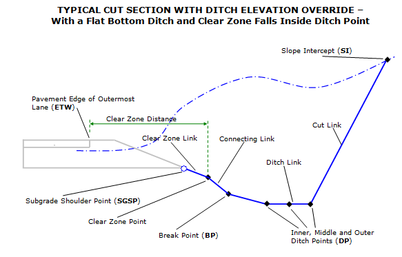
- A ditch link is inserted from ditch bottom inside point to ditch bottom outside point using Ditch Width or Outside Ditch Width Target.
- Check elevation on surface at ditch bottom outside point, if the ditch elevation is above surface elevation, this SA functions in the same way it would if Override Ditch Bottom Elevation is set to No and a message is sent to the event viewer.
- If the clear zone distance is wider than the distance between the subgrade shoulder point and the outside ditch point, a second clear zone link is inserted at the outside ditch point ends at the clear zone distance.If the second clear zone link is shorter than Minimum Width of Connecting Link input value, it will be extended to a width equal to Minimum Width of Connecting Link, unless daylight surface is encountered.If daylight surface is encountered by second clear zone link, second clear zone link will terminate at the daylight surface. To close to the daylight surface in cut:
- If Override Backslope of Final Link Intersecting Daylight Surface Type is set to No, the intercept to the daylight surface is calculated using the Flat Rate of Cut Slope value.
- If the height of the flat cut slope exceeds the Max Height, the intercept to the daylight surface is re-calculated using the Steep Rate of Cut Slope value.
If Override Backslope of Final Link Intersecting Daylight Surface Type is set to anything other than No, then the Final Link is defined using the parameter set in Override Backslope of Final Link Intersecting Daylight Surface Value1 or Value 2 (depending on the Type set), rather than the Flat and Steep Rate of Cut Slope.
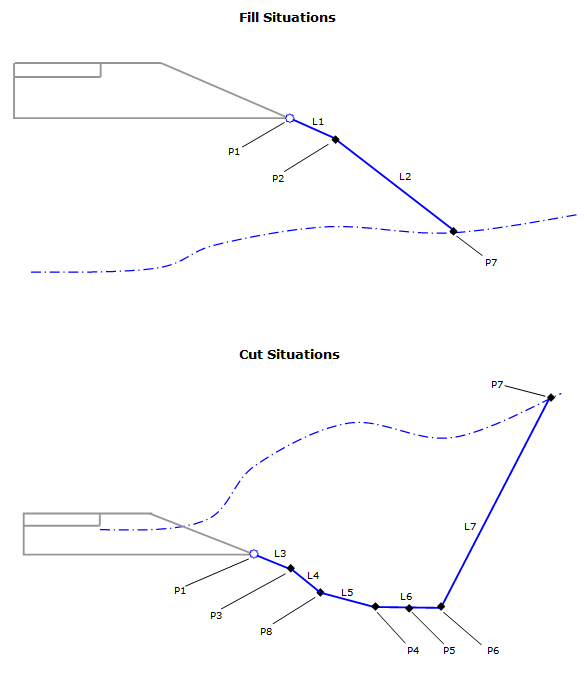
Attachment & layout mode operation
The attachment point is at the start of the first link, which is the rotation point link in fill or the foreslope link in cut. The subassembly is typically attached to the outside edge of the roadway, such as the subgrade shoulder point, back of sidewalk or back of curb. This component can be attached to either the left or right side.
In layout mode, this subassembly shows both the cut and fill condition flat-slope solutions in dashed lines.The daylight links are extended outward for a horizontal distance of 10 feet and terminate with arrowheads pointing outwards.
Input parameters
Info: All dimensions are in feet unless otherwise noted. All slopes are indicated as a percent slope with a "%" sign.
| Parameter | Description | Type | Default |
|---|---|---|---|
| Side | Specifies which side to place the subassembly | Left / Right | Right |
| Foreslope Slope | Slope of the ditch foreslope link (cut only) | Slope, positive | 6:1 |
| Foreslope Width | Width of the ditch foreslope link (cut only) | Numeric , positive | 8.0 ft |
| Bottom Width | Width of the bottom of the ditch | Numeric, positive | 0.0 ft |
| Clear Zone Distance | Width of the clear zone measured from the pavement (ETW) edge of the outermost lane. | Numeric, positive | 20.0 ft. |
| Clear Zone Slope | Slope of Clear Zone Slope | Slope , positive | 4:1 |
| Offset to Measure Clear Zone From | Offset, measured from the baseline, used to start clear zone measurement from. This can be obtained from the ETW Offset distance of the adjacent lane with a Parameter Reference, or will use fixed value here. The distance from the attachment point to the end of the clear zone link is then computed as Clear Zone Distance – (offset of the attachment point – Offset to Measure Clear Zone From). Offset is always a positive value to the right of baseline alignment and a negative value to the left | Numeric | 12 ft. |
| Minimum Fill Height | In fill sections where the distance between the subgrade shoulder point and the Daylight Surface is less then this value, a cut section may be constructed. | Numeric, positive | 1.0 ft. |
| Optional Ditch in Small Fill Situations | Option to construct a cut section if the minimum fill height is not met. | Yes/No | Yes |
| Ditch Depth in Small Fill | If a cut section is created due to the Minimum Fill Height input, the depth specified here is measured down from where a projected Foreslope link intersects the daylight surface. Foreslope Slope and Foreslope Width inputs are used to determine the minimum length of the foreslope link; however if by applying the Ditch Depth in Small Fill criteria, the foreslope link is longer then the inputted Foreslope Width value, then this longer length is used. | Numeric, positive | 1.0 ft. |
| Distance to Rotation Point | Distance to the rotation point measured from the pavement (ETW) edge of the outermost lane. | Numeric, positive | 20.0 ft. |
| Offset to Measure Rotation Point From | Offset, measured from the baseline, used to start Distance To Rotation Point measurement from. This can be obtained from the ETW Offset distance of the adjacent lane with a Parameter Reference, or will use fixed value here. The distance from the attachment point to the end of the rotation point link is then computed as Distance To Rotation Point – (offset of the attachment point – Offset to Measure Distance to Rotation Point From). Offset is always a positive value to the right side of baseline alignment and a negative value to the left | Numeric | 12.0 ft. |
| Fill Slope to Rotation Point | Slope of the rotation point link. This value may be obtained from the adjacent shoulder through the use of a parameter reference. | Slope , positive | 6:1 |
| Override Ditch Bottom Elevation | Specifies that the elevation of the ditch point will be calculated based on something other than the slope and width of the foreslope link. Keeps slope value while varying width. | String, Combo List of options: a.) No, b.) Elevation, c.) Profile | No |
| Ditch Bottom Elevation | Elevation to use when overriding the elevation of the ditch point in cut sections. | Numeric, positive | 800.0 ft |
| Connecting Link Slope | When an elevation, profile or profile list is used to control the elevation of the ditch bottom point, the slope entered here defines the slope of the link between the end of the clear zone link and the ditch point. | Slope, positive | 4:1 |
| Minimum Width of Connecting Link | Minimum width of the connecting link. When a connecting link is defined to be narrower then the inputted value, the slope of the connecting link will be set to use the Foreslope Slope parameter, not the Connecting Link Slope parameter. Also minimum width of clear zone links. When a clear zone link is defined to be narrower than inputted value, the width of the clear zone link will be extended to the minimum. | Numeric, Positive | 8.0 ft. |
| Include Daylight Link Omit Daylight Link | Include or omit the Final Link | Include / Omit | Include |
| Max Height | Height used to determine whether slope of Cut Slope or Fill Slope uses flat or steep rate. | Numeric, positive | 10.0 ft. |
| Steep Rate of Cut Slope | Default slope rate of last link in cut when depth of cut is greater then Max Height. | Slope, positive | 2.5:1 |
| Flat Rate of Cut Slope | Default slope rate of last link in cut when depth of cut is less then Max Height. | Slope, positive | 4:1 |
| Steep Rate of Fill Slope | Default slope rate of last link in fill when depth of fill is greater then Max Height. | Slope, positive | 3:1 |
| Flat Rate of Fill Slope | Default slope rate of last link in fill when depth of fill is less then Max Height. | Slope, positive | 4:1 |
| Override Backslope of Final Link Intersecting Daylight Surface Type | Overrides the steep/flat rate of final cut or fill slope used to intersect the Daylight Surface. Option Width means the absolute distance value from the attachment point, while option Offset is measured from the baseline alignment and can be a negative value. | String, Combo List of options: a.) No, b.) Width, c.) Offset, d.) Slope, e.) Target Object | No |
| Override Backslope of Final Link Intersecting Daylight Surface Value1 | The distance or offset value to use when overriding the backslope of the final link intersecting the Daylight Surface. When Offset is specified as the Override Type, a negative value indicates an offset to the left of the baseline. | Numeric | 0.0 |
| Override Backslope of Final Link Intersecting Daylight Surface Value2 | The slope value to use when overriding the backslope of the final link intersecting the Daylight Surface. | Slope, run-over-rise | 0 |
Target parameters
This section lists the parameters in this subassembly that can be mapped to a target object such as a surface, alignment, or profile object in a drawing. For more information, see Setting and Editing Targets in the AutoCAD Civil 3D User's Guide Help.
| Parameter | Description | Status |
|---|---|---|
| Daylight Surface | Name of the Surface for Daylighting. The following object types can be used as targets for specifying this surface: surfaces | Required |
| Ditch Point Elevation | Object used to determine the bottom of the ditch in a cut section. Profile specified must be a child of the baseline alignment. The following object types can be used as targets for specifying this elevation: profiles, 3D polylines, feature lines, or survey figures. | Optional |
| Foreslope Width | Object that defines the outside edge of the foreslope link. The following object types can be used as targets for specifying the width: alignments, polylines, feature lines, or survey features. This target only works when Override Ditch Bottom Elevation is set to No, otherwise, the outside edge of the foreslope (that is also the inside ditch bottom point) is determined by other parameters in the logic described later. | Optional |
| Outside Ditch Width | Object that defines the Outside Ditch Point. The following object types can be used as targets for specifying the width: alignments, polylines, feature lines, or survey figures. If this target falls inside inside ditch point, it will be ignored. Setting this target overrides Bottom Width parameter. | Optional |
| Clear Zone Distance | Object that defines the clear zone location in cut sections. The following object types can be used as targets for specifying the width: alignments, polylines, feature lines, or survey features. | Optional |
| Rotation Point Distance | Object that defines the rotation point location in fill sections. The following object types can be used as targets for specifying the width: alignments, polylines, feature lines, or survey features. | Optional |
| Final Link Target Object | Object that defines the location of the end of the final link (P7) when Override Backslope of Final Link Intersecting Daylight Surface Type is Target Object. The following object types can be used as targets for specifying the width: alignments, polylines, feature lines, or survey features. | Optional |
Output parameters
None
Point, Link, and Shape codes
| Point/Link/Shape | Codes | Description |
|---|---|---|
| P1 |
SGSP Hinge Hinge_Fill Hinge_Cut |
Fill condition only – attachment point for fill rotation point link. Cut Condition only – attachment point for first cut link. |
| P2 |
Rotation_Point Hinge Hinge_Fill |
Fill condition only – rotation point. |
| P3 | Clear_Zone | Cut condition only – Clear Zone Point |
| P4 |
Ditch_Point Label_Ditch Ditch_In |
Cut condition only – inner ditch point. Cut condition only – ditch point to label station-out |
| P5 | Ditch_Point | Cut condition only – middle ditch point. |
| P6 |
Ditch_Point Label_Ditch Ditch_Out |
Cut condition only – outer ditch point. Cut condition only – ditch point to label station-out |
| P7 |
SI Daylight Daylight_Cut (this is used in cut only) Daylight_Fill (this is used in fill only) |
Slope Intercept (Daylight) Point in Cut and Fill |
| P8 |
Break Point Hinge Hinge_Cut |
Cut Condition only – break between connecting link and ditch foreslope. |
| L1 |
Datum Top Label1 |
Finished Grade Surface with code for optional labeling. |
| L2 |
Datum Top LABELSLP |
Finished Grade Daylight Link with code for optional labeling. |
| L3 |
Datum Top LABEL1 |
Finished Grade Surface with code for optional labeling. |
| L4 |
Datum Top LABEL2 |
Finished Grade Surface with code for optional labeling. |
| L5 |
Datum Top LABEL3 |
Finished Grade Surface with code for optional labeling. |
| L6 |
Datum Top LABEL4 |
Finished Grade Surface with code for optional labeling. |
| L7 |
Datum Top LABELSLP |
Finished Grade Daylight Link with code for optional labeling. |