CGGen
Last updated: 2021-02-12
 Description
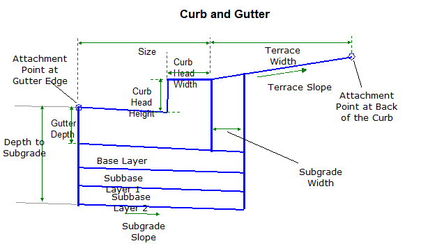
The CGGen subassembly inserts links for a standard shape representing concrete curb and gutter with optional base course layers. Dimensions of the shape are controlled by curb and gutter types per WisDOT Standards. See WisDOT Standard Detail Drawings for further information on curb shape and dimensions.
Behavior
Curb shape and dimensions are derived from WisDOT standard detail drawings as shown in the WisDOT Facilities Development Manual. Curb selection from standard detail drawing is determined by inputs for Curb and Gutter Type, Size, and Curb Head Height.
Integral Curb designation will not affect subassembly construction of the curb, it is used for proper assignment to pay item in quantity takeoff.
If the Gutter Slope Method selected is Use Outside Lane SE or Use Inside Lane SE, the gutter slope only deviates from a slope of Gutter Slope when inserting the subassembly on a superelevated high side where the superelevation defined for the baseline alignment exceeds 2%. The methodology is further explained below.
- If Gutter Slope Method is set to Use Outside Lane SE or Use Inside Lane SE, the subassembly uses the baseline alignment's SE to determine the gutter slope. The gutter slope will be Gutter Slope unless the SE exceeds 2%. Where SE exceeds 2%, the gutter slope will equal the SE rate for the baseline alignment.
- If Gutter Slope Method is set to Fixed Slope, the slope of the gutter will follow the value of the Gutter Slope parameter.
-
If Gutter Slope Method is set to Fixed Slope, once an Assembly has been built, the user has the option to set a parameter reference in Assembly Properties and use the Pavement Slope of an adjacent lane to define the gutter slope.
Bottom of curb link is parallel to gutter slope.
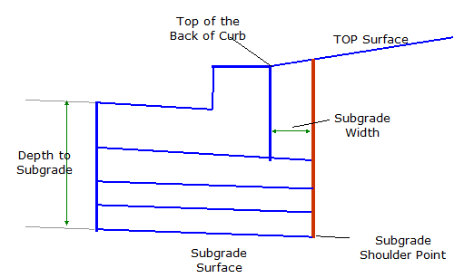
Various base course layer depths can be defined, however the Depth to Subgrade must be non-zero. This value defines the depth to the bottom of the lowest base course layer. If the Base Depth entered is greater then the Subbase Depth entered, then Subbase Depth is equal to the Base Depth. If the Depth to Subgrade input is less then either the Base Depth or the Subbase Depth, then the Depth to Subgrade will be equal to the greater of the two values. The subgrade surface is inserted to the back of curb, and continues for a distance defines by the Subgrade Width input. From the subgrade shoulder point, a nearly vertical link (small constant width from the bottom to the top to allow it to be modeled in a surface - shown in red in the diagram below) is inserted up to the intersection with the TOP surface. All base course layer links extend to the intersection with this nearly vertical link, as shown in the diagram.
When subgrade links are inserted, subgrade slope is controlled by the Subgrade SE Method parameter. User also has the option of entering a fixed slope to be used, following the insertion side Outside Lane SE defined for the baseline alignment, following the insertion side Inside Lane SE defined for the baseline alignment, using the Outside Lane SE defined for the baseline on the opposite side, which is then multiplied by -1.0 or using the Inside Lane SE defined for the baseline on the opposite side, which is then multiplied by -1.0. When Subgrade SE Method is set to Fixed Slope, this slope can be controlled using a Parameter Reference that sets the slope equal to that of the subgrade surface of an adjacent lane. In all situations, the slopes of all base course surfaces will follow the slope of the subgrade surface.
If the Terrace Width input is less than Subgrade Width input, a link is inserted from the Top of the Back of Curb for a distance defined by the Subgrade Width. Slope of the link is defined by the Terrace Slope input.
User has the option of setting Parameter References for Base and Subbase course depths, as well as the Depth to the Subgrade Surface using the depths of these same surfaces output from the adjacent lanes.
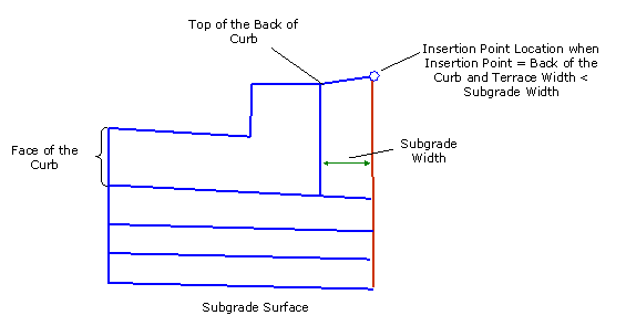
The subassembly builds the shape for a simple curb and gutter, with the attachment point either at (a) inside gutter edge or (b) back of the curb or terrace point if a Terrace Width input is non-zero. If the Insertion Point input is set to Back of the Curb, and Terrace Width is less than Subgrade Width, the insertion of the subassembly will begin at a distance behind the curb and gutter defined by the Subgrade Width. If both Terrace Width and Subgrade Width are 0 and the Insertion Point is set to the Back of the Curb, then the insertion of the subassembly will begin at the Top of the Back of the Curb.
Dev Note: If the Insertion Point is Back of the Curb then
- Assign (0,0) point to P4 when Terrace Width and Subgrade Width are both 0;
- Assign (0,0) point to P14 when Terrace Width < Subgrade Width.
-
Assign (0,0) to point P15 when Terrace Width > Subgrade Width.
See the coding diagram for point locations. The location of the rest of the points are computed. In otherwords, the coding diagram as illustrated below is retained, no matter where the attachment point is located.
Attachment & layout mode operation
The attachment point is at the flange point of the gutter or back of the curb.
In layout mode the subassembly displays the curb-and-gutter component based on the Input parameters given. Subgrade and other base course layers are shown at a slope of -2% and the gutter slope is drawn at -6.25%.
Input parameters
Info: All dimensions are in feet unless otherwise noted. All slopes are in run-over-rise form (for example, 4:1) unless indicated as a percent slope with a "%" sign.
| Parameter | Description | Type | Default |
|---|---|---|---|
| Side | Indicates which side the subassembly is inserted towards. | Left/Right | Right |
| Insertion Point | Specifies insertion point of the curb and gutter |
String, Combo List of options: a) Gutter Edge; b) Back of the Curb |
Gutter Edge |
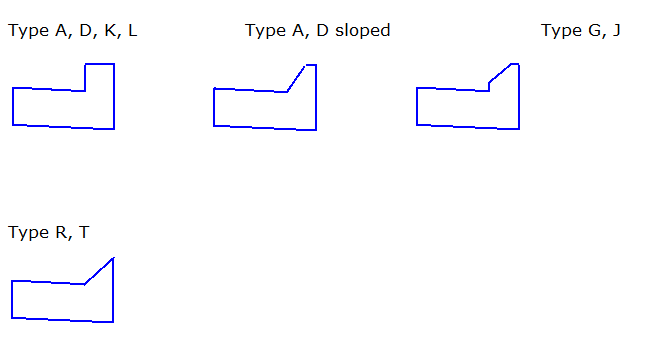
| Curb and Gutter Type | Type of curb and gutter to construct, "sloped" suffix indicates sloped curb head when it is an option for that curb type. |
String, Combo List of options: A ; A-sloped ; D ; D-sloped ; G ; J ; K ; L ; R ; T ; K-Optional Curb ; L-Optional Curb |
A |
| Size (inches) | Curb and Gutter Size. Size is the horizontal distance from the back of curb to the flange of curb. |
Numeric, List of options: 6; 18; 30; 36 |
30" |
| Curb Head Height (inches) | Vertical distance from the flowline to the top of the curb head. |
Numeric, List of options: 4; 6 |
6 |
| Integral Curb? (Y/N) | Assigns curb quantity to integral curb pay item when answered "Yes" . Integral curb is an option for Curb types D, J, and L only. |
String, Combo List of options: a) Yes; b) No |
No |
| Gutter Slope Method | Specifies method of gutter slope calculation. If using either Outside Lane SE or Inside Lane SE, slope in normal crown is equal to Gutter Slope and only changes when slope exceeds 2% on the high side. Remains Gutter Slope on low side. |
String, Combo List of options: a) Fixed Slope; b) Use Outside Lane SE; c) Use Inside Lane SE |
Use Outside Lane SE |
| Gutter Slope | Specifies fixed gutter slope. | Slope | -6.25% |
| Base Depth | Distance to the bottom of the first base course layer. This measurement is taken from the top of the pavement. If there is no base course layer, a zero depth should be specified. | Numeric, Non-negative | 0.0 |
| Subbase Depth | Distance to the bottom of the second base course layer. This measurement is taken from the top of the pavement. If there is no second base course layer, a zero depth should be used. | Numeric, Non-negative | 0.0 |
| Depth to Subgrade | Depth to subgrade at the flange point. Cannot use a zero depth. The depth specified here should be the depth to the bottom of the last base/subbase course layer. | Numeric, positive | 1.5' |
| Subgrade Width | Distance the base/subbase courses are extended beyond the back-of-curb. Use zero to terminate the base/subbase courses at the back-of-curb. | Numeric, Non-negative | 1.0' |
| Subgrade SE Method | Selects whether to use the superelevation slope defined for the baseline alignment, if it exists, for the subgrade surface or to set a fixed numeric % slope value. If Fixed Slope is specified, once an Assembly has been built, the user has the option to set a parameter reference in Assembly Properties and use the Subgrade Slope of an adjacent lane to define the subgrade slopes of the curb and gutter. |
String, Combo List of options: a) Fixed Slope; b) Use Outside Lane SE; c) Use Inside Lane SE; d) Use the Opposite Side Outside Lane SE Multiplied by -1.0; e) Use the Opposite Side Inside Lane SE Multiplied by -1.0 |
Use Outside Lane SE |
| Fixed Subgrade Slope | Cross slope of the subgrade surface. This value is used if Fixed Slope is the Subgrade SE Method selected, or SE is not defined for the baseline alignment. | Slope | -2% |
| Terrace Width | Width of the terrace, measured from the top of the back of curb. | Numeric,non-negative | 6.0' |
| Terrace Slope | Slope of the terrace. | Numeric | 4% |
Target parameters
None
Output parameters
None
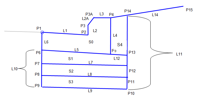
Point, Link, and Shape codes
| Point/Link/Shape | Codes | Description |
|---|---|---|
| P1 | Flange | Flange point of the gutter |
| P2 | Flowline_Gutter | Gutter flowline point |
| P2 | (type)_(size)_(head ht)_(INT) | Feature line creator for identifying QTO pay item. ‘INT' suffix is only added to the code when Integral Curb (Y/N) input is "Y". |
| P3, P3A | TopCurb | Top-of-curb |
| P4 | BackCurb | Back-of-curb |
| P6 | In_Pave1_CG | Crown Point at the bottom of the flanged portion of the curb and gutter |
| P7 | In_Base1_CG | Crown Point on Base Layer (optional) |
| P8 | In_Base2_CG | Crown Point on Base Layer (optional) |
| P9 | In_Sub_CG | Crown Point on top of subgrade |
| P10 | ETW_Sub_CG | Outside edge of subgrade under C&G |
| P11 | ETW_Base2_CG | Outside edge of Base 2 layer under C&G |
| P12 | ETW_Base1_CG | Outside edge of Base 1 layer under C&G |
| P13 | ETW_Pave1_CG | Outside Edge of top of first base layer under C&G |
| P14 | ETW_Datum_CG | Outside Edge of the FINGRND surface behind C&G |
| P15 | CG_Terrace | Terrace Point behind curb and gutter |
| L1-L3 | Top, Curb | Finish grade on the curb and gutter |
| L4 | Curb | |
| L5 |
Curb Pave1 |
|
| L6 | Curb | |
| L7 | Base1 | |
| L8 | Base2 | |
| L9 |
SUBG Datum Subbase |
|
| L11 |
SUBG Datum Subbase |
Link from point P10 to point P14 |
| L12 | Pave1 | |
| L13 | Top | Link from P4 to P14 |
| L14 |
Datum Top |
Link from P14 to P15 |
| S0 | Curb | |
| S1 | Base1 | Only created when Base Depth > 0 |
| S2 | Base2 | Only created when Base Depth and Subbase Depth are both > 0. |
| S3 | Subbase | If Base Depth and Subbase Depth are 0, Subbase is only shape created. |
| S4 | CurbBackfill | Only created when Subgrade Width > 0 |