Intersection assemblies
Last updated: 2026-01-06
Intersection
 Curb Return Fillet
Description
This assembly is used to model the curb return regions at intersections. All curb return alignments should run in the same direction (clockwise) so this one assembly will be used for all 4 quadrants. The baseline for this assembly is the curb and gutter flange alignment. The width of the LnExtendBase pavement is based on targeting the outside of mainline pavement and typically the centerline of the side road.
Construction
- Baseline
- Left
- LnExtendBase
CGBasic
- Left
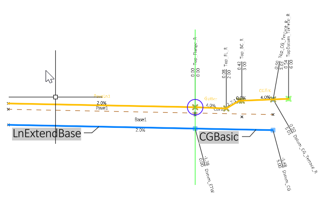
LnExtendBase – This subassembly is used to model the lane portion of the curb return quadrant of an intersection. The Inside base extension width parameter is used to model the subgrade and base layers beneath the curb and gutter. All crown point codes are removed. The crown feature lines are developed with another baseline along the side road centerline.
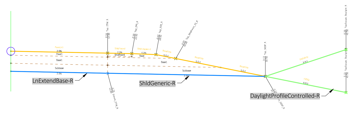
Rural Full Section
Description
This is a basic assembly for use on a typical 2-lane rural road.
Construction
- Baseline
- Right
- LnExtendBase-R
- ShldGeneric-R - Shoulder lane layer thicknesses are obtained through parameter references of the adjacent lane layer thicknesses
- DaylightProfileControlled-R
- Left
- LnExtendBase-L
- ShldGeneric-L - Shoulder lane layer thicknesses are obtained through parameter references of the adjacent lane layer thicknesses
DaylightProfileControlled-L
- Right
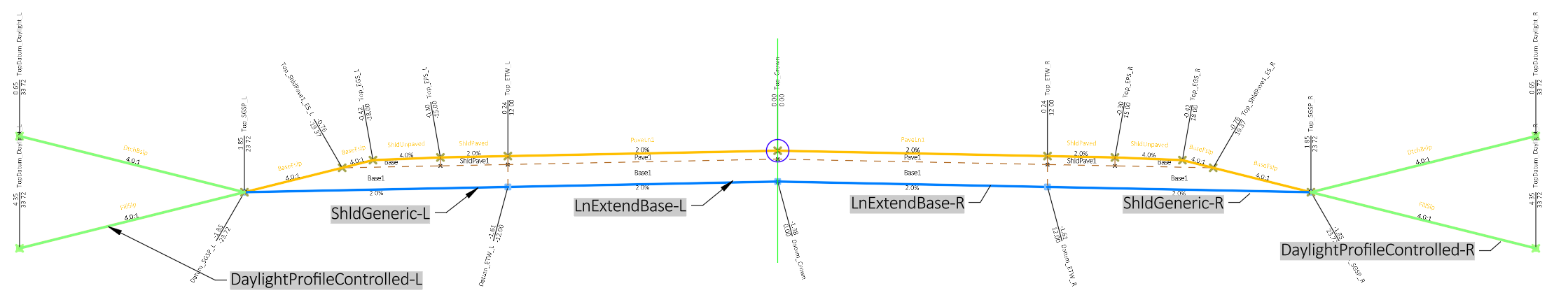
LnExtendBase-L – This subassembly is used to model the left inside lane.
ShldGeneric-L– This subassembly is used to model the left shoulder. Parameter references adjacent lane layer thicknesses
DaylightProfileControlled-L– This subassembly is used to model the left daylight including ditching. Parameter references outside edge of lane offset to measure recoverable slope from.
LnExtendBase-R– This subassembly is used to model the right inside lane.
ShldGeneric-R– This subassembly is used to model the right shoulder. Parameter references adjacent lane layer thicknesses
DaylightProfileControlled-R– This subassembly is used to model the right daylight including ditching. Parameter references outside edge of lane offset to measure recoverable slope from.
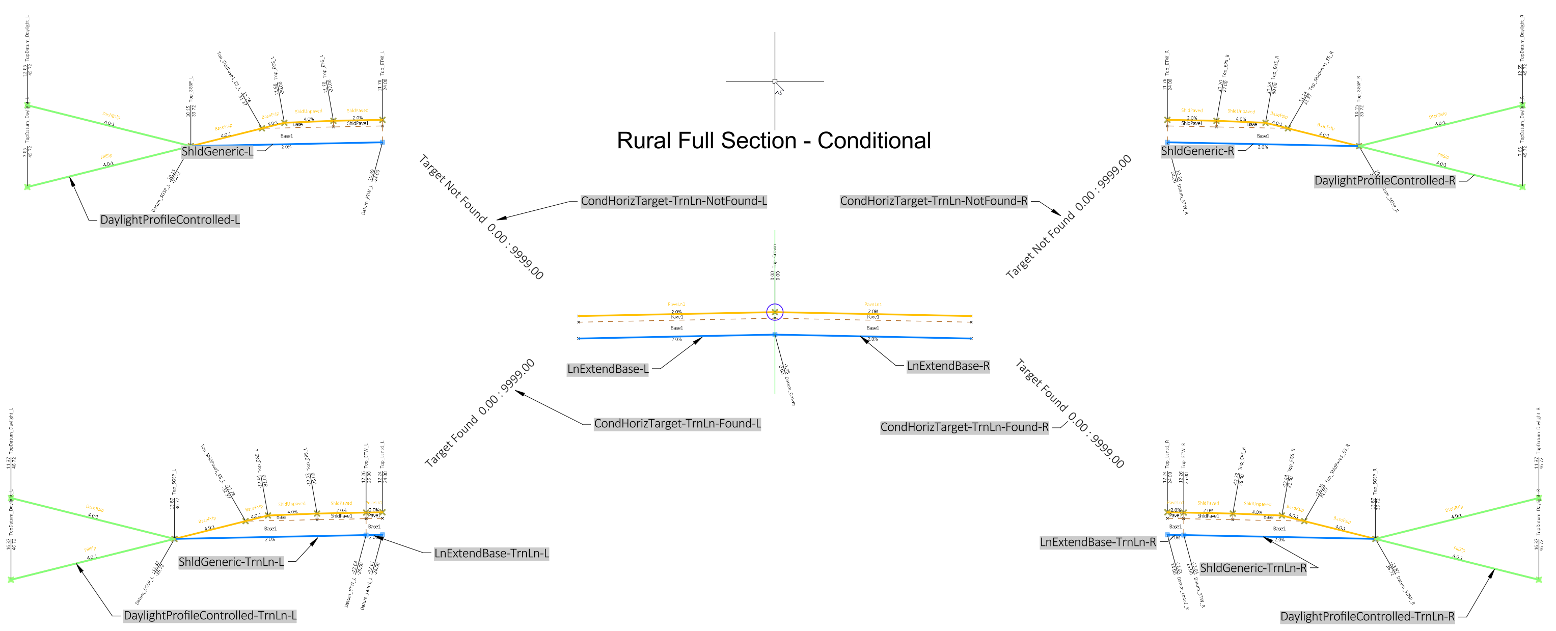
Rural Full Section - Conditional
Description
Conditional subassemblies automatically add specified subassemblies to an assembly based on whether a target is found at a corridor frequency. This is an example assembly for use on a typical 2-lane rural road with a conditional for turn lanes through an intersection. This assembly can be used as an alternative to using multiple corridor regions through an intersection area.
Construction
- Baseline
- Right
- LnExtendBase-R
- CondHorizTarget-TrnLn-Found-R - turn lane found condition right side
- LnExtendBase-TrnLn-R - add turn lane right side
- ShldGeneric-TrnLn-R
- DaylightProfileControlled-TrnLn-R
- CondHorizTarget-TrnLn-NotFound-R - turn lane NOT found condition right side
- ShldGeneric-R
- DaylightProfileControlled-R
- Left
- LnExtendBase-L
- CondHorizTarget-TrnLn-NotFound-L - turn lane NOT found condition left side
- ShldGeneric-L
- DaylightProfileControlled-L
- CondHorizTarget-TrnLn-Found-L - turn lane found condition left side
- LnExtendBase-TrnLn-L - add turn lane left side
- ShldGeneric-TrnLn-L
DaylightProfileControlled-TrnLn-L
- Right
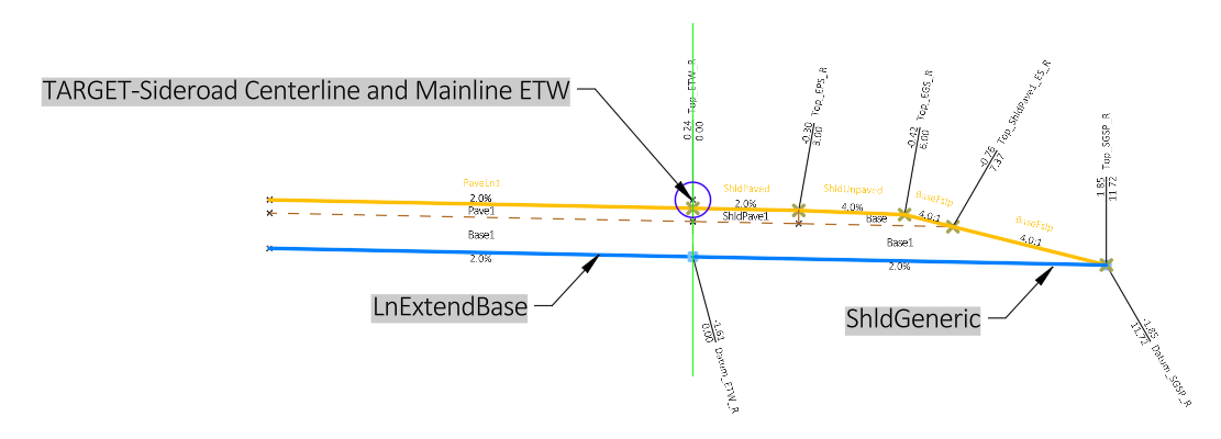
Shoulder Return Fillet
Description
This assembly is used to model rural shoulder returns. All shoulder return alignments should run in the same direction (clockwise). The baseline for this assembly is the edge of intersection quadrant pavement.
Construction
- Baseline
- Right
- TARGET-Sideroad Centerline and Mainline ETW (edge of travelled way) LinkOffsetAndElevation sub
- LnExtendBase no crown points, they are developed with other assemblies
ShldGeneric Shoulder lane layer thicknesses and slopes are obtained through parameter references of the adjacent lane
- Right
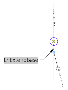
Sideroad CL
Description
This assembly is intended to be used only in the scenario where two return fillets (Curb Return Fillet or Shoulder Return Fillet) touch together and there are no lanes between them. The fillet assemblies do not code a point at the end of the LnExtendBase as that is handled by mainline lanes. Where there are no lanes, this "stick" assembly will code the centerline/crown.
Construction
- Baseline
- Right
LnExtendBase
- Right
This assembly consists of 1 LnExtendBase subassembly with zero width.
Roundabout
Four of the Roundabout assemblies are setup to target the inside baseline to the left first, then the assembly targets back to the right.
- Rndbt Curb Right-Lane Left-No Crown Code
- Rndbt Curb Right-2 Lanes Left-No Crown Code
- Rndbt Left Crown Code
-
Rndbt Rural Shoulder Right-Lane Left-No Crown Code
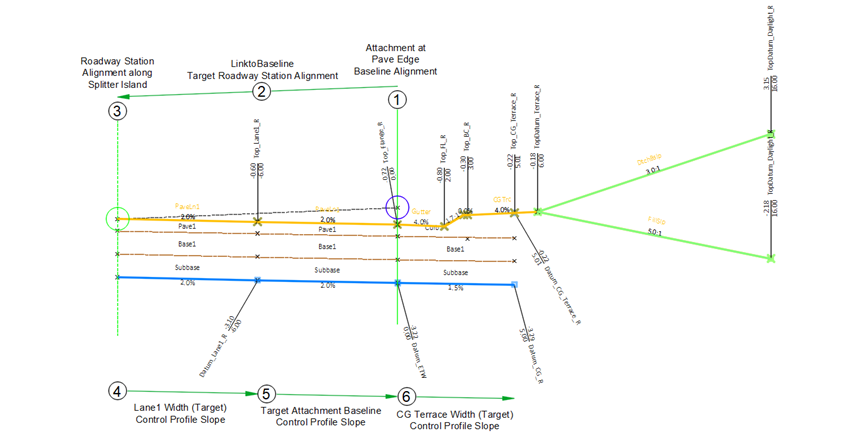
General construction of above assemblies
- Attachment point.
- The assembly is built to first target the inner geometry alignments and profiles of the roadway, usually either the primary or secondary station alignment along the curb flange of the splitter island.
- The location of the primary or secondary alignment where the rest of the subassemblies begin to target geometry to the right.
- A LnExtendBase subbassembly lane width targets towards a lane, curb flange or shoulder target depending on the assembly. A control profile may be used to target the slope.
- A LnExtendBase subbassembly targets towards a lane, curb flange or edge of pavement target depending on the assembly. The slope can be provided by using a parameter reference of the inside lane slope or a control profile is used to target the slope.
-
If the assembly has a curb on the outside, the outer extension widths of the LnExtendBase subbassembly targets the CG terrace width. If the assembly has a shoulder on the outside, the paved an/or aggregate shoulder target the shoulder geoemetry alignments.
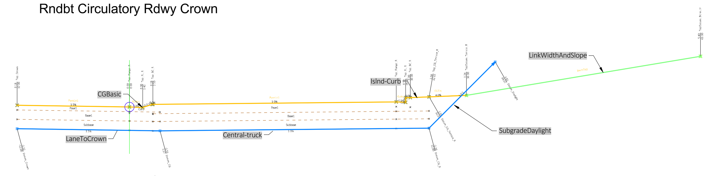
Rndbt Circulatory Rdwy Crown
Description
This assembly is used to model the central island and circulatory roadway region of a roundabout. The baseline alignment should run in clockwise direction.
Construction
- Baseline
- Left
- LaneToCrown
- Right
- CGBasic
- Central-truck
- Islnd-Curb
- LinkWidthAndSlope
SubgradeDaylight
- Left
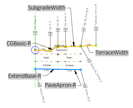
Rndbt Curb Return Right-Truck Apron
Description
This assembly is used to model the outer curb return regions of a roundabout. It includes an option to provide a pave truck apron. All curb return alignments should run in the same direction (clockwise) so this one assembly will be used for all curb return quadrants.
Construction
- Baseline
- Right
- ExtendBase-R
- Right (2)
- CGBasic-R
- PaveApron-R
- SubgradeWidth
TerraceWidth
- Right
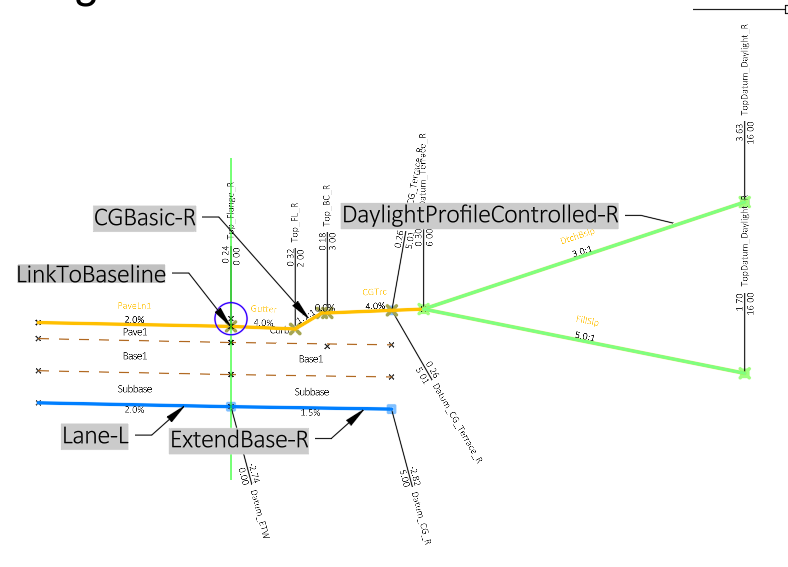
Rndbt Curb Right-Lane Left-No Crown Code
Description
This assembly is used in sections of the approach roadways where only one lane and a curb are required and there is a splitter island or a paved median on the inside. It is setup to target the inside baseline to the left first (inside towards splitter island), then the assembly targets back to the right (outside). No Point code is set along the inside of the assembly since the splitter island assembly will provide the curb flange code. The first target link from the attachment point is set to “Omit link”.
Construction
- Baseline
- Left (2)
- LinkToBaseline
- Lane-L
- CGBasic-R
- ExtendBase-R
DaylightProfileControlled-R
- Left (2)
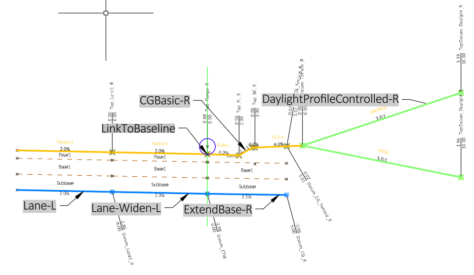
Rndbt Curb Right-2 Lanes Left-No Crown Code
Description
This assembly is used in sections of the approach roadways where two lanes and a curb are required and there is a splitter island or paved median on the inside. It is setup to target the inside baseline to the left first (inside towards splitter island), then the assembly targets back to the right (outside). No Point code is set along the inside of the assembly since the splitter island assembly will provide the curb flange. The first target link from the attachment point is set to “Omit link”.
Construction
- Baseline
- Left (2)
- LinkToBaseline
- Lane-L
- Lane-Widen-L
- CGBasic-R
- ExtendBase-R
DaylightProfileControlled-R
- Left (2)
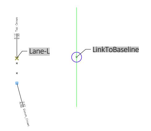
Rndbt Left Crown Code
Description
This assembly is used in sections of the approach roadways where either the “Rndbt Curb Right-Lane Left-No Crown Code” or the “Rndbt Curb Right-2 Lanes Left-No Crown Code” have been used and there is a paved median. This assembly supplies the coding of the inside edge of the lane along the paved median. The first target link from the attachment point is set to “Omit link”.
Construction
- Baseline
- Left (2)
- LinkToBaseline - target edge of lane left of baseline
Lane-L - models crown only, no width
- Left (2)
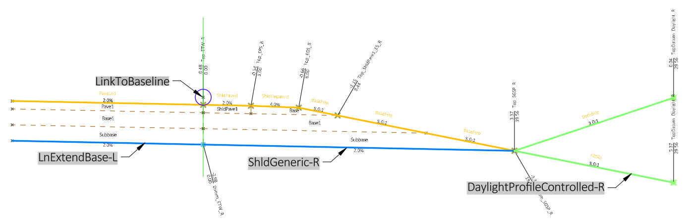
Rndbt Rural Shoulder Right-Lane Left-No Crown Code
Description
This assembly is used in sections of the approach roadways where only one lane and a shoulder are required and there is a splitter island or a paved median on the inside. It is setup to target the inside baseline to the left first (inside towards splitter island), then the assembly targets back to the right (outside). No Point code is set along the inside of the assembly since the splitter island assembly will provide the curb flange code. The first target link from the attachment point is set to “Omit link”.
Construction
- Baseline
- Left (2)
- LinkToBaseline - target edge of lane left of baseline
- LnExtendBase-L - models lane back to baseline
- ShldGeneric-R
DaylightProfileControlled-R
- Left (2)
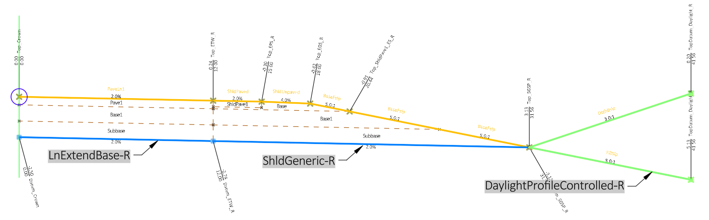
Rndbt Rural Half Section Right
Description
All the subassemblies in this assembly attach to the right. This assembly is used in sections of the approach roadways where only one lane and a shoulder are required. It is used to model section of the approach roadway that does not have a splitter island or paved median and defines the inner crown feature.
Construction
- Baseline
- Right
- LnExtendBase-R
- ShldGeneric-R
DaylightProfileControlled-R
- Right
Rndbt Rural Half Section Right-No Crown Code
Description
All the subassemblies in this assembly attach to the right. This assembly is used in sections of the approach roadways where only one lane and a shoulder are required It is used to model section of the approach roadway that does not require a crown code.
Construction
- Baseline
- Right
- LnExtendBase-R - no crown codes
- ShldGeneric-R
DaylightProfileControlled-R
- Right