Data for Construction - Create Verification Surface
Last updated: 2026-01-06
Overview
The tool is run from the breakline raw data file. It copies the pertinent breakline and boundary data into a new file and creates a new surface from that data. The design surface is data referenced into the drawing and a verification surface is created (volume surface) to compare the design surface and breakline surface.
Using the Command
- Open a breakline file. The tool works using the breakline raw data file produced by the WisDOT Design Surface Data Extractor or breakline files created using other methods.
- WisDOT Design tab > Output panel > Data for Construction dropdown > Create Verification Surface
- The tool can also be accessed from the command line: DOTCREATEVERIFICATIONSURFACE.
Create Verification Surface dialog box
Tooltips are available for all the controls.
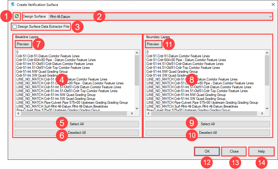
- Refresh
- Refreshes the dialog after a Data Shortcut Project change.
- Design Surface
- Surface to compare the Verification Surface to. Commonly a Refinement Surface. The Verification Surface is the surface created from the breaklines in the current file.
- Design Surface Data Extractor Files check box
- Check this box if the current drawing is a breakline raw data file produced by the WisDOT Design Surface Data Extractor. Layer and object recognition is automated for these files. Breaklines on the "LINE_NO_MATCH" layers are not transferred to the verification surface drawing. See Extract design surface data utility overview.
All the layer information in the dialog box will be grayed out when the Design Surface Data Extractor box is checked. 2. The message "Not a Design Surface Data Extractor breakline file." will appear if the box is checked but breaklines were not extracted using the WisDOT tool.
Breakline Layers
- Select the layers with breakline information. Layers are selectable when the Design Surface Data Extractor File box is not checked.
- Breakline Layers - Drawing layer list
- List of layers in the current drawing. Select individual layers that contain breaklines.
- Breakline Layers - Select All
- Picks all layers in the current drawing
- Breakline Layers - Deselect All
- No layers in the current drawing will be used
- Breakline Layers - Preview
Toggle on/off switch to highlight all the objects on the selected breakline layers.
Boundary Layers
-
Select the layers with boundary information. Layers are selectable when the Design Surface Data Extractor File box is not checked.
- Boundary Layers - Drawing layer list
- List of layers in the current drawing. Select the layers containing the boundary objects.
- Boundary Layers - Select All
- Picks all layers in the current drawing
- Boundary Layers - Deselect All
- No layers in the current drawing will be used
- Boundary Layers - Preview
- Toggle on/off switch to highlight all the objects on the selected boundary layers.
- Create Surface
- A new drawing is created using the current WisDOT design template.
- Selected breakline and boundary objects are copied to the new drawing
- The new drawing contains 3 surfaces:
- Design Surface (data referenced)
- < Design Surface > - FromBreaklines (surface created from selected breaklines and boundary)
- < Design Surface > - Verification (volume surface; base surface = Design Surface, comparison surface = surface from breaklines). The analysis ranges are set for elevations less than 0.01 foot and greater than 0.01 foot.