Profile - Control Profile Editor
Last updated: 2026-02-24
Overview
The Control Profile Editor was developed by WisDOT to quickly create profiles without the need for a profile view.
The profile object has traditionally been used to establish elevation values for roadway features such as centerline, curb and gutter, or special ditches. Profile elevations can also be leveraged for other purposes. Think of the profile elevations acting as nothing more than numeric value containers. Those numeric values can represent not only elevation, but other parameters such as length, width, height, or slope.
These profiles can be used as corridor targets to control various parameters of subassemblies. These can be dimensional (length, width, height, etc.) or slope parameters. By using the Civil 3D profile object to control these parameters, designers can create smooth transitions or trigger various subassembly behavior. This tool can also be used to develop PVI-only profiles, such as special ditch elevations. The tool is not intended for creating or editing profiles that include vertical curve components.
Usage
WisDOT Design tab > Design panel > Profile menu > Control Profile Editor
The Control Profile Editor can also be accessed from the command line: DOTCONTROLPROFILEEDITOR, or the from the Alignment right click menu.
The Control Profile Editor includes two tabs; Create and Edit.
Behavior
The Control Profile Editor runs on a modeless dialog, so the user can interact with Civil 3D while the tool is open. The dialog includes a minimize button on the title bar so it can be reduced to the taskbar when additional screen space is needed.
If a drawing includes control profiles, the Control Profile Editor opens to the Edit tab. If there are no control profiles in the drawing, it opens to the Create tab. When launching the Control Profile Editor from an alignment right click menu, it opens with that alignment selected in the dialog.
The Control Profile Editor fully supports Station Equations. All values entered in the dialog are the station values with equations. The raw station (station value as if no equations are used) is displayed in the profile table for reference.
The Control Profile Editor includes input value validation. If there is an issue with an input value, an red icon is displayed next to the input. Hover the mouse over the icon to see why the input did not pass validation.
Create tab
The Create tab is where a profile is initially created. To create a profile, a parent alignment must first be selected. The profile requires three initial values; the start station, the end station, and the value (elevation). For the purpose of this tool, elevation is referred to as "Value" since the elevation can represent many different types of parameters (ex. slope, width, elevation, logical switches).
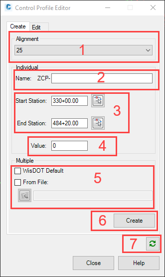
- Select the alignment that will be the parent of the profile.
-
Enter a new profile name in the New Profile Name box. A name prefix of "ZCP-" is hard-coded into the new name.
Info: The "Z" is for profile list organization purposes. The "Z"puts all of the control profiles at the bottom of the list (alphabetically) in the TOOLSPACE > Prospector tab. "CP" stands for Control Profile.
Warning: The Control Profile Editor will only interact with profiles that have the "ZCP-" prefix and do not have any curves. Therefore, if profiles are created outside of this tool they will need to be named or re-named with a "ZCP-" prefix in order to interact with the Control Profile Editor interface.
- By default, the parent alignment station limits are automatically populated in these boxes when the alignment is selected. The values can be changed by either editing the station value in the box, or by using the buttons and picking stations in model space.
- Set the default value for the profile here. In most cases, these should be the dominant values for the profile range on the project. For example, if the profile will be used to control ditch backslopes throughout the project and the predominate slope is 4:1, you would either enter 0.25 (ft/ft) or 4: (Run:1) for this value. The Control Profile Editor will instantaneously convert values entered as Run:1 to ft/ft. It will also instantaneously convert values entered as % to ft/ft.
- Optionally, control profiles can be created in bulk by reading a .csv file. Selecting the Use WisDOT Default option will read the prebuilt CSV located here: C:\ProgramData\Autodesk\ApplicationPlugins\WiXX.X.bundle\Contents\en-US\CreateSlpCntlProfs.csv
- This file can be edited to match the project standard values. This file can also be copied to another location and edited there.
- You will likely need/want to edit the values before creating the profiles. The values can be edited directly in the csv file, and the Control Profile Editor provides an opportunity to make changes right before creation.
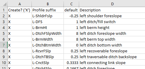
- The Create? ('X') column controls whether or not a profile for that variable is created. Insert "X" for any profile you want to create.
- The Profile suffix column contains standard object naming content and should not be edited.
- The default column contains the default begin and end values for the control profile. Some values like recoverable foreslope and daylight slope may need to be edited depending on the project.
Below is a sample of left side only values in the .csv file.
- You will likely need/want to edit the values before creating the profiles. The values can be edited directly in the csv file, and the Control Profile Editor provides an opportunity to make changes right before creation.
- A different .csv file can be selected using the From File: options.
- Make sure to save and close the .csv file before creating the profiles.
- This file can be edited to match the project standard values. This file can also be copied to another location and edited there.
-
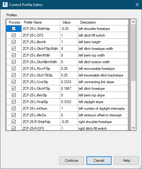
Once the desired profile parameters have been entered, click Create . When creating an individual profile, a message will appear indicating the profile has been created. When using the multiple profiles option, a new dialog will appear allowing you to preview the profiles for creation. Here, there is an opportunity to make changes to the profiles prior to creation and select/deselect specific profiles for processing. Changes made in this dialog do not alter the contents of the input csv file. When ready, click the Continue button to create the selected profiles.
- Refresh All to reread the drawing database. This can be used to refresh the information in the Control Profile Editor from the current drawing if changes to the drawing are not reflected in the Control Profile Editor.
Edit tab
The Edit tab is where station/value pairs, or PVIs can be added, edited, or deleted.
Warning: This interface must be refreshed when using the Undo button.
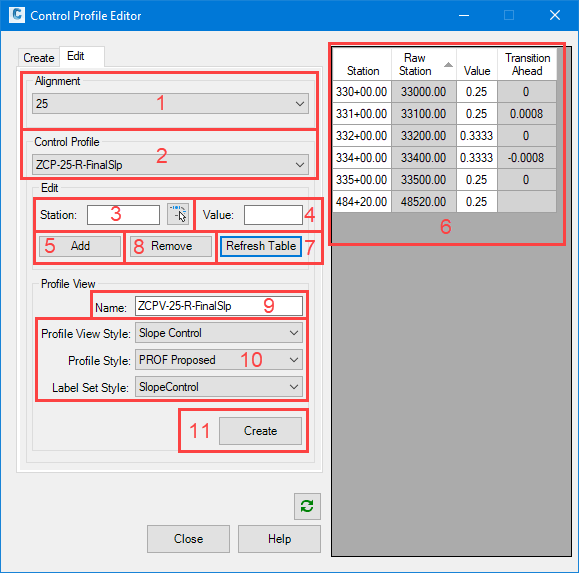
- Select the parent alignment of the profile to be edited. Only alignments that have Control Profile children are listed.
- Select the profile to be edited from the Control Profile drop-down list.
- To add a station location or PVI, type a station in the Station box or select the station in model space using the button.
- Calculate station based on distance from existing station
- If a station is highlighted in blue in the table, typing +=<distance value> will calculate an increased station and typing -=<distance value> will calculate a decreased station based on the highlighted station.
- Calculate station based on distance from existing station
- Enter the desired value or PVI elevation in the value box.
- Auto-translate ratio or percent Value to decimal
- If a ratio (X:1) or percent (%) is entered, values will automatically be converted to decimal.
- Auto-translate ratio or percent Value to decimal
- Once the PVI station and value have been entered, click Add to add the PVI to the profile. If the parent alignment contains station equations that result in the possibility of multiple instances of the specified station, a dialog will appear asking for the desired instance based on raw station.
- The Profile Table is where the PVIs are listed. This is an interactive table, where values can be changed by clicking on the cells. The Raw Station column is read-only and automatically computed. The Transition Ahead column is read-only and automatically computed. This column represents the slope of the profile ahead of the PVI (change in value/distance).
- Auto-translate ratio or percent Value to decimal
- If a ratio (X:1) or percent (%) is entered, values will automatically be converted to decimal.
- Auto-translate ratio or percent Value to decimal
- PVIs can be copied from one profile to another. To copy PVIs, select the PVIs in the table. Right click and choose Copy PVI(s) to Profile. This option is only available if more than one control profile exists under the parent alignment. Select the destination profile from the drop-down menu and click OK. To apply new elevation values to the copied PVIs, check the "Apply new value" box and specify the new value. To offset the source PVI elevation values, check "Offset source value" box and specify the offset amount. To copy the source PVI elevations as-is, do not check either box. The PVIs will be copied to the destination profile and the destination profile will be activated. PVIs can only be copied to control profiles with the same parent alignment. If a PVI station already exists in the destination profile, it will not be overwritten.
- To remove values, select the station(s) in the Profile Table, then click Remove. The beginning and ending PVI cannot be removed.
-
If a profile view is desired, enter the name of the profile view in this box. A name is automatically populated based on the Control Profile name, but this can be edited.
Info: The "Z" is for profile list organization purposes. The "Z" puts all of the slope/width control profile views at the bottom of the list (alphabetically) in theTOOLSPACE > Prospector tab. "CPV" stands for Control Profile View.
- Select the desired profile view style, profile style, and label set style. If the drawing contains the profile view style Slope Control, the profile style PROF Proposed, and label set style SlopeControl, these style swill be populated as the default.
- Create to place the profile view in model space.
-
The Refresh Table button refreshes the values in the Control Profile Editor Profile Table.
Info: This is only necessary when the profile has been edited in the Civil 3D interface, either with the Civil 3D Profile Layout Tools, or with grip edits.