Pipe Network - Swap Parts List Styles
Last updated: 2016-03-11
Total video time: 07:24
pipe-ntwrk-swp-prts-lst-styl-tl.mp4 07:24
Overview
Review of previous WisDOT workflow
In previous WisDOT Civil 3D standards files the user would create a pipe network using a pipe network template. Then, any plan production drawings would be created using a base template. The templates were created separately to help keep drawing sizes manageable. Pipe networks reference the parts list to assign styles when data referencing. The base template did not contain the parts lists to create the pipe networks, so the styles would be incorrect upon data referencing the pipe network. The workflow required importing the pipe network parts list(s) from the source pipe network drawing prior to creating the data reference in the plan production drawing.
Current WisDOT workflow
The base template and the pipe network template were combined to create a single base design template. This was achievable after the base design template size was reduced by removing all unused AutoCAD components and making them available through the ribbons and palettes. The base design template now includes all of the parts lists, pipe styles, and structure styles necessary for both plan production and design scenarios. There is no longer a need to import a parts list into a plan production drawing created from this template before creating a pipe network data reference. (Note: If a custom parts list was created for a pipe network, that parts list will still need to be imported into corresponding production drawing prior to creating a pipe network data reference.)
In the WisDOT base design template, the assigned pipe and structure styles are set to plan production styles. This assures that all data references of the pipe network will appear with the correct plan-view style. However, during the design process, it is typically desirable to view the pipes and structures as a 3D model in all views. In a standard Civil 3D environment, this would normally require changing the assigned pipe styles and structure styles in the drawing manually after they are placed. To avoid this additional work, WisDOT has created the Swap Parts List Styles utility. This utility is intended to only be used on pipe network source (design) drawings. The utility changes the styles of all the chosen parts to a "design" or "3D model" style. If desired, it will also change the style for any previously placed pipes and structures.
Usage
WisDOT Design tab > Design panel> Pipe Network dropdown > Swap Parts List Styles
The tool can also be accessed from the command line: SWAPPARTSTYLES.
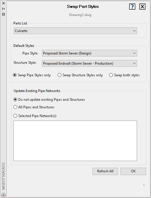
- Select a Parts List.
- Select default styles for Pipe Style and Structure Style.
- Swap Pipe Styles only or Swap Structure Styles only or Swap both styles.
- Select Do not update existing Pipes and Structures (parts list only) or All Pipes and Structures or Selected Pipe Network(s) only.
- Refresh All to see a current list of pipe networks available (if choosing that option).Note: "Refresh All" button available in Civil 3D 2018 only.
- Select Pipe Network(s) from list (if choosing that option).
- OK to update styles.