Corridor - Shrink Wrap Corridor Surface
Last updated: 2026-06-02
Overview
This command will creates a shrink wrap boundary for the selected corridor surface based on the selected point and/or link codes. The command works by computing a separate boundary for each corridor region based on the selected point and/or link codes. Then, the final boundary is computed by merging the separate region boundaries.
Since the command computes the boundary region by region, point and/or link codes need to be selected that will form a enclosed boundary for every region, not just for the overall corridor. Using Select By Surface Definition will typically assure all of the necessary point and/or link codes are selected. However, in certain situations, additional codes may need to be selected to augment the boundary definition.
The created boundary is not added to the corridor definition. Instead, the boundary is added to the corridor surface definition. The boundaries created by this command can be removed by running the command without any point and link codes selected. This will return the corridor surface to it's initial state.
Usage
WisDOT Design tab > Design panel > Corridor menu > Shrinkwrap Corridor Surfaces
The tool can also be accessed from the command line: DOTSHRINKWRAPCORRIDORSURFACES.
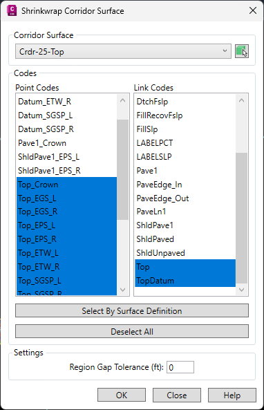
- Surface:
- Select a surface from the menu.
- Point Codes:
- Select point codes from the list to include in the boundary definition (or select none). Use Shift or Ctrl buttons to select multiple point codes.
-
Link Codes:
Tip:Even if the surface is not defined by links, best results can be achieved by adding the appropriate links to the boundary definition.
For Crdr-Top surfaces, include the “Top” and “TopDatum” links in the boundary definition. For Crdr-Datum surfaces, include the “Datum” links in the boundary definition.
- Select link codes from the list to include in the boundary definition (or select none to clear existing boundaries). Use Shift or Ctrl buttons to select multiple link codes.
- Select By Surface Definition
- Use this button to auto-select the codes based on the surface definition. (recommended)
- Deselect All
- Use this button to clear the point and link code selections.
- Region Gap Tolerance:
- Enter a value for the widest gap the command will cross between regions to continue the boundary line. The resulting surface will not triangulate across gaps that are greater than or equal to the given Region Gap Tolerance as measured along the baseline.