Visibility Check - Check Sight Distance
Last updated: 2026-01-06
Overview
This tool checks for sight distance obstructions utilizing input parameters for object height, required stopping, decision or passing sight distance, and terrain surface. Obstruction surfaces can also be included as part of the sight analysis. The tool provides options to create a report, sight distance profiles and sight lines.
The eye height used is 3.5 feet above the terrain surface. The tool can be used to analyze projects based on the standards located in FDM 11-10-5.1.1 Stopping Sight Distances (SSDs); Decision Sight Distances (DSDs) and FDM 11-10-5.1.3 Passing Sight Distances.
Differences between Civil 3D version and WisDOT version
WisDOT version:
- measures along the path, not alignment
- allows for multiple obstruction surfaces
- reports which surface is impairing visibility
- labels sight distance achieved at each sight line
- creates sight distance profile
Using the Command
WisDOT Design tab > Analyze panel > Visibility Check dropdown > Check Sight Distance
The tool can also be accessed from the command line: DOTCheckSightDistance.
Sight Distance dialog box
Tooltips are available for all the controls.
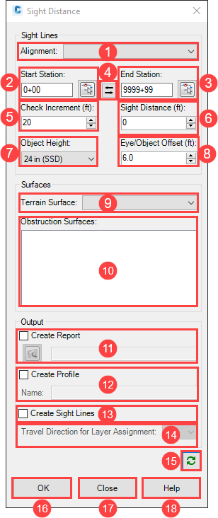
Sight Lines
- Alignment - centerline alignment to perform analysis along
- Start Station
- Enter start station or
- Use button to select start station from drawing
- Default is alignment start station
- End Station
- Enter end station or
- Use button to select end station from drawing
- Default is alignment end station
- Reverse
- Swaps start and end station
- Automatically switches the direction of travel for (14.) Travel Direction for Layer Assignment
- Output report and profile should be renamed if the analysis direction is reversed
- Check Increment (ft) - The interval along the alignment to perform the sight distance analysis
- Sight Distance (ft) - The required sight distance. See FDM 11-10-5.1 Sight Distances
- Object Height - Height of object to be seen by the driver. Text in parenthesis is included in the sight line layer name.
- 24 in (SSD), Stopping Sight Distance
- 24 in (DSD), Decision Sight Distance
- 42 in (PSD), Passing Sight Distance
- Eye/Object Offset (ft) - Offset distance the driver's eye and object are located from the alignment. Positive values are always to the right of the alignment based on the direction of travel.
- Two lane roadways - distance from centerline to center of travel lane
- Multilane roadways - distance from outside lane edge to the center of outside lane.
Surfaces
- Terrain Surface - Ground surface that will be evaluated
- For proposed designs, it is recommend that a Cmbn-Ex-Top surface is created (a combination of the refinement Top surface with the existing ground surface) for this analysis.
- Obstruction Surfaces
- Select surface(s)
- Multiple surfaces can be selected by using the Ctrl-click for individual surfaces within the list or Shift-click for a range of surfaces that are consecutive in the list of surfaces.
- Use Ctrl-click to deselect an obstruction surface.
- See Surfaces - Create Wall Surface for additional information.
Output
- Create Report - check the box to create a csv file of the results
- Create Profile - check the box to create a profile that represents the sight distance (y-axis) based on station location (x-axis)
- Create Sight Lines - check the box to draw sight lines based on the Check Increment and Sight Distance values.
- Travel Direction for Layer Assignment - NB, SB, EB, WB are included in the layer naming for the created sight lines
Dialog box controls
- Refresh
- Refreshes the dialog after a drawing change. Therefore, the dialog box can remain open while switching between drawings.
- OK - runs the command, a progress bar appears while calculations are performed
- Close - closes the dialog box
- Help - opens the Civil 3D Knowledge Base homepage
Output
Report
See example report for report format.
The listed sight distance values will not exceed the required sight distance entered in the dialog. Longer sight distances may be available based on the surrounding terrain.
The note "Surface data missing along path. Results may not be accurate." is included at locations where surface data is missing along the path analysis.
The tool also reports which surface is impairing visibility at each increment where the required sight distance has not been achieved.
Profile
The sight distance values along the y-axis will not exceed the required sight distance entered in the dialog. Longer sight distances may be available based on the surrounding terrain.
A profile view must be created to see the sight distance profile.
Sight Lines
Behavior
Three dimensional lines are created within the analysis range set by the Start and End Station.
From:
Station: Check Increment station location
Offset: Eye Offset from alignment
Elevation: 3.5 feet above the Terrain surface elevation located at the given Station/Offset
To:
Station: End station location is determined by the sight distance reported along the Alignment from the starting Check Increment station location.
Sight distance is the distance along the vehicle path throughout which an object of specified height is continuously visible to the driver. The location of the vehicle path is determined by the eye offset.
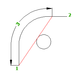
When an obstruction is encountered, the obstructed sight lines are drawn in the manner shown below. The command reports the actual sight distance ("3" in the image below) as the distance along the vehicle path between the eye ("1" in the image below) and the furthest point of visibility along the vehicle path towards the target (the target is "2" in the image below).
If alignment and surface data DOES NOT exist at the analyzed sight distance, a visible sight line is drawn that is truncated to the alignment or surface data limits
Offset: Eye Offset from alignment
Elevation: Object Height above Terrain surface elevation located at the given Station/Offset
Labels
Each sight line is labeled with the sight distance at that location.
Near the limits of the analyzed surface, distance labels have an asterisk next to them to indicate that the tool could no longer find a surface in the analysis area.
Note: Sight distance adjustments for roadway grades is not included in this tool (See Table 3-2, page 3-6, 2018 AASHTO GDHS).
Layers
Each sight line is an AutoCAD Line object. All of the sight lines are combined into an AutoCAD Group object. This allows for the selection of all the sight lines in order to delete, hide or isolate them at the same time, while still maintaining the flexibility of layer control on the lines.
If an individual element within the group requires a manual edit, set the PICKSTYLE variable to 0. This makes each element in the group selectable. When editing is complete, set the PICKSTYLE variable back to 1.
The tool creates the following layers (based on input parameters). If the layer already exists, then that layer will be used.
Layer naming format:
SIGHT_ < analysis type > _ < Travel Direction >_ SightDist < Met/Reduced > _ < Object Height > _ObjHt
- SightDistMet = required sight distance has been achieved (layer color is green)
-
SightDistReduced = required sight distance has not been achieved because of the terrain or an obstruction (layer color is red)
Example layer names:
- SIGHT_SSD_NB_SightDistMet_24in_ObjHt
- SIGHT_SSD_NB_SightDistReduced_24in_ObjHt