Roadway design requirements, tips, info, and warnings
Last updated: 2026-01-06
 Create corridor surfaces as early as you can in the design process.
When creating a design corridor, create the corridor surfaces immediately along with it. Maintain the corridor surface feature line list as the design concept evolves. Inspect these surfaces as design modifications are made.
A design can look OK in the corridor, but it might not be structured properly to make corridor surface development as easy as it should be. This structural problem in the corridor data can lead to significant design rework if it isn't identified early. Fortunately there is an easy way to see these problems. They show up visibly in the surface models.
Significant time will be spent reworking design if corridor surfaces are not created early and the resulting surface models inspected as the design progresses.
Why corridor links are not allowed to define, or help define corridor surfaces:
Methods hears this question frequently, presumably because the use of corridor links would save time in defining and maintaining the definition of corridor surface models. Making the use of corridor links even more attractive is the "overhang correction" functionality in corridors that helps clean up areas of vertical links in our corridor surfaces. With all these benefits tied to the use of corridor links in surface definition, why does WisDOT require corridor surfaces be defined by corridor feature lines only?
Let's discuss the Design Model deliverables before answering this question. Here are a few key aspects of the Design Model deliverables:
- The principle component of Design Model packages are surface models. The surface models communicate design intent clearly, more so than the other deliverables in the Design Model.
- Proposed surface model longitudinal breaklines are also an important deliverable. Some contractors will choose not to use Design Model surface models in construction operations, and will instead develop their own sets of surface models that suit their construction operations and workflows. Contractors who anticipate following this practice have clearly stated that the longitudinal breaklines of proposed surfaces will be most useful to them in their Construction Model development efforts.
- The primary source of longitudinal breaklines in the Design Model surface models is the list of corridor feature lines used to define corridor surfaces.
- It is critical that all the data in Design Models be:
- Consistent with the plan
- Consistent with itself
- Must be complete, with no missing information.
Again, why not use corridor links to define surface models?
- One reason is that using corridor links to define corridor surfaces significantly increases the risk that the designer will not specify all the needed corridor feature lines in the corridor surface definition, leading to delivery of an incomplete set of breaklines in the Design Model package. By adding corridor links to the definition, the designer will fix problems in the corridor surface related to missing corridor feature lines. This is bad. Those problems should be visible to the designer, not hidden or fixed behind the scenes. If corridor links are not used in surface definition, the absence of needed corridor feature lines will be clearly visible to the designer, especially in corridor section editor. When corridor links are used in the surface definition, the missing corridor feature line problems are hidden from the designer making it very easy to deliver an incomplete set of longitudinal breaklines in the Design Model. The end result: a Design Model package with surface models that are inconsistent with breaklines. This is a deal-breaker as far as the use of corridor links is concerned, WisDOT deliverable requirements will disallow use of corridor links in corridor surface definition until this problem is resolved.
- Overhang correction functionality cleans up surface model triangulation in areas of vertical links, but it does not correct the problem in the longitudinal breaklines. If overhang correction is used to fix these problems in design, the problems will reappear when contractors use Design Model breaklines to develop Construction Model surfaces. See 3. How can I correct vertical link problems in my proposed surface models without using "overhang correction" with corridor links in the corridor surface definition, or without using a surface edit actions on the refinement surface? #fix-vert-link for a method to collect these vertical link problems without using "overhang correction".
- Longitudinal breakline data leads to better, more consistent roadway surface model triangulation than cross sectional patterned data. This is a similar concept as survey collection. Originally WisDOT collected survey data for DTM surfaces in the traditional cross sectional collection pattern. Experience taught us that longitudinal breakline collection of roadway data results in better triangulation overall, and survey collection practices changed to a longitudinal feature based collection pattern for existing ground surface models. The same is true for proposed surface models. Many times that triangulation from cross sectional elements, such as corridor links, is OK. But some situations that commonly appear in roadway terrain areas will triangulate incorrectly with cross sectional based data, use of longitudinal roadway features (corridor feature lines) corrects those triangulation errors.
Vertical links
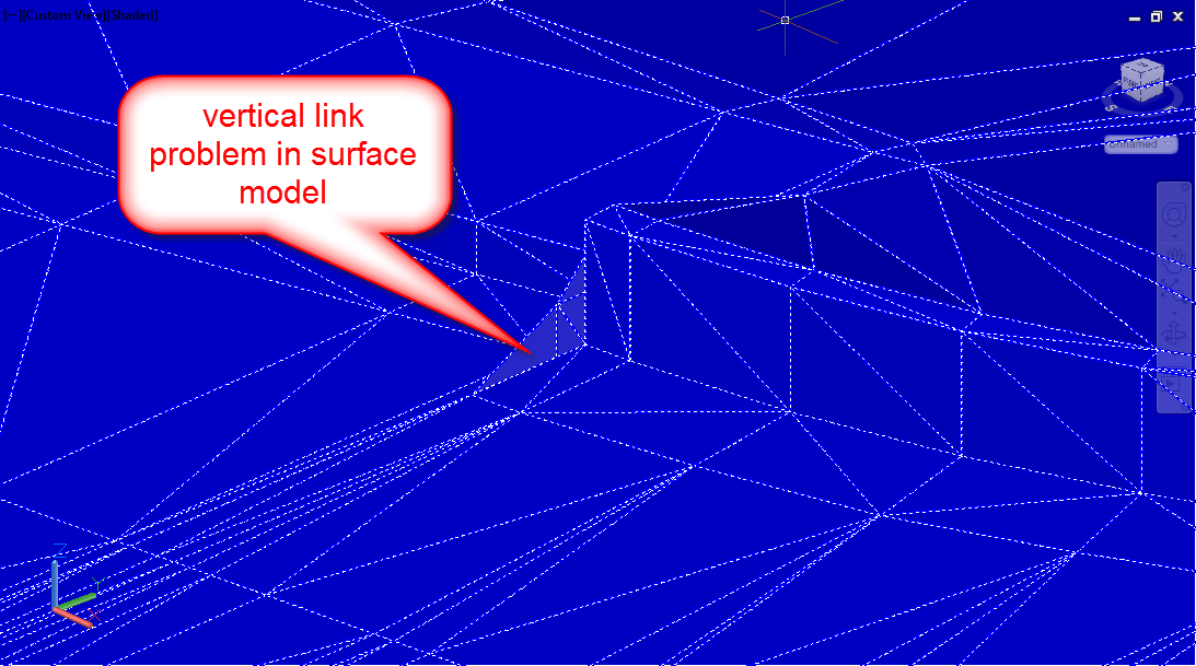
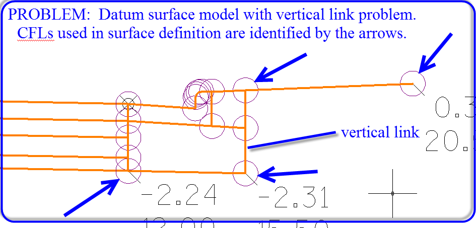
3. How can I correct vertical link problems in my proposed surface models without using "overhang correction" with corridor links in the corridor surface definition, or without using a surface edit actions on the refinement surface? #fix-vert-link
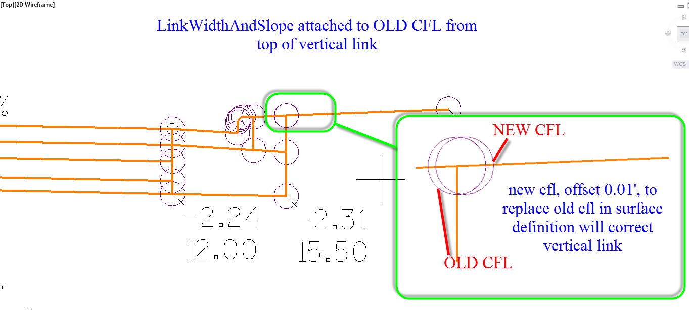
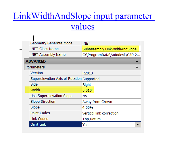
- A vertical link is created when 2 corridor feature lines (CFLs) that are the same offset distance from the baseline, are both used in defining the same surface model. Fix the vertical link problem by inserting LinkWidthAndSlope subassembly to your assembly.
- Using a generic link subassembly like LinkWidthAndSlope, create a new CFL to replace one of the old CFLs from the vertical link. Offset the new CFL from the old CFL by 0.01'. Use the new CFL in the corridor surface definition, remove the old CFL from the corridor surface definition.
System performance
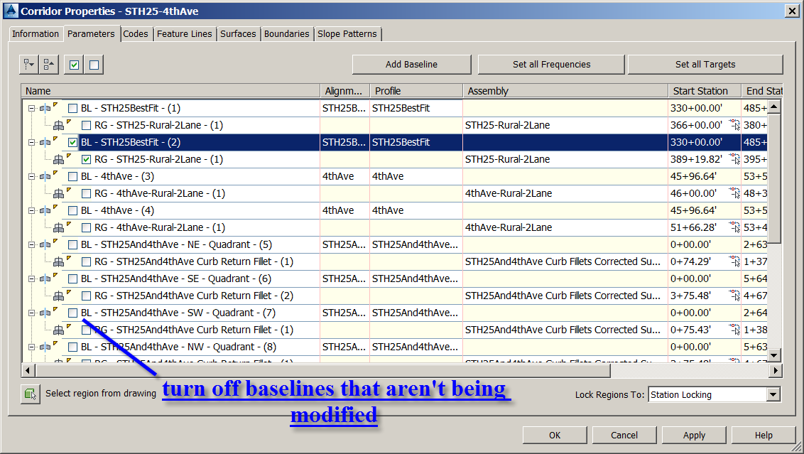
When modifying corridors, turning off all baselines that are outside the area you are working in will improve system performance. When finished working with the corridor turn all baselines back on and rebuild the corridor before saving and closing the DWG file, this will ensure the corridor surfaces are completely constructed through the full extents of the corridor.
Parameter overrides
Avoid using "Parameter Overrides" to make changes to your corridor. Make the needed to changes to the input parameter values in your assemblies instead.
Parameter overrides will save time when initially used, but will cost you much lost time overall.
Parameter overrides are tied to a station, not a location in coordinate space. If baseline stationing shifts, parameter overrides are all incorrect and must be redone.
Design changes are difficult to execute within corridors that are heavy on parameter overrides.
Changes made in parameter overrides are much less visible in the design data than are independent assemblies and regions.
Info: Parameter overrides can be a useful tool for experimenting with results of different input parameter values. But once the correct input parameter solution is identified, remove the parameter overrides and implement the changes with a copy of the assembly and new corridor region.
Conditional subassemblies
Explore using conditional subassemblies ConditionalHorizontalTarget and ConditionalCutOrFill in your designs.
These can save a lot of time in design by: consolidating multiple typical section scenarios within a single assembly, reducing corridor structure complexity by reducing number of regions.
ConditionalHorizontalTarget makes transition locations between typical sections easier to adjust because the locations are defined by a target object that can be moved easily. ConditionalCutOrFill makes it easier to manage multiple daylighting solutions within a single assembly/region. There are many other timesaving uses of conditional subassemblies, they are very flexible tools that open up opportunities for creative corridor design solutions.
Use a target oriented philosophy in corridor design
Don't try to manage all the roadway cross section geometry changes with input parameters, use horizontal and vertical target objects to define geometry when you can. Create target objects for applicable horizontal roadway features.
Use single object representation in design data
Don't have multiple objects representing the same thing, use a single object and reference it when needed. Design changes are much easier to manage when this approach is followed.
- Example: Use the same objects for corridor targeting that are used for plan sheet roadway feature graphics. Doing so will help keep plan sheets and Design Models synchronized.
Viewing surfaces
Don't just look at surfaces in the corridor section editor. This only tells part of the story. Orbit around the surface to look for problems early and often.
Building corridors
Build as much of your design as you can in the corridor. You can do more than you think there.
Building surfaces
Refinement surfaces represent the current state of your design. Corridors are one source of refinement surface definition, but feature lines and other 3D linework can also be used as breaklines and/or grading surfaces.
Intersections
Build corridors from intersections outward. Designing in Civil 3D is easier if this is done.
Assemblies
Use copies of assemblies in different regions rather than reusing the same assembly in multiple regions
Unintended changes can occur to a design when there are multiple regions using the same assembly. The assembly could be modified for a specific situation, forgetting the modification will be applied to the other regions. It is better to have multiple identical assemblies of different names than it is to have a single assembly used multiple times.
Combining surfaces
Projects with multiple design corridors can combine multiple corridor surfaces (of the same type) into a single refinement surface by using multiple "Paste" operations.
Subassembly types
Use both WisDOT subassemblies and Autodesk subassemblies.
The 2 subassembly libraries can be used effectively in the same design.
The one problem with this in practice is the combining of WisDOT subassemblies with Autodesk subassemblies using Axis of Rotation (AOR) superelevation functionality. Use of AOR requires differences in baseline superelevation definition that are not compatible with WisDOT subassemblies. See Don't use WisDOT subassemblies in the same baseline (horizontal reference line) as Autodesk subassemblies with Axis of Rotation (AOR) superelevation functionality. #dont-mix-sub.
Subassembly with superelevation functionality
Don't use WisDOT subassemblies in the same baseline (horizontal reference line) as Autodesk subassemblies with Axis of Rotation (AOR) superelevation functionality. #dont-mix-sub
Use of AOR requires differences in the baseline's superelevation definition that are not compatible with WisDOT subassemblies. If you need to use Autodesk AOR subassemblies in your design, don't use the WisDOT subassemblies with slope control by superelevation on the same baselines as the Autodesk AOR subassemblies.
Generic links
It is possible to build your entire roadway assembly with generic link subassemblies. That may not be the best way to construct an assembly, but thinking that way can help solve unique assembly problems for which there is no subassembly.
Downstream design
Keep the data flowing down stream. (Follow the Civil 3D Project Data Map)
There is a uni-directional flow to the data relationships in the WisDOT roadway design workflow, the Civil 3D Project Data Map depicts this idea. Keeping this concept in mind will help keep your project data structured and operating correctly, and help you avoid data problems such as circular references.
Target naming
For subassemblies that require targeting, name them so you know what the target should be. Example name: TARGET-ETW AliProf and SideRoad AliProf
Dividing corridors
A corridor can easily be broken apart into multiple corridors in separate files, but multiple corridors cannot be combined together easily.
Surface profiles
Do not create data shortcuts of surface profiles. Instead, data reference the surface and create the surface profile in each drawing it is needed.
This practice reduces the total amount of objects in your data shortcut list. This practice will also make it easier to avoid circular references, and it may improve system performance in some situations.
Surface edit tools
Avoid use of surface editing tools. It is better to make changes through corridor tools, or use of feature line and 3D linework as breaklines, and the Civil 3D grading tools.
Use of surface edit tools will make changes to the surface model, but those changes will not be in the breakline delivery for those surfaces, leading to Design Model data inconsistency. These design changes can be made in a way that will promote better data consistency.
Example: using the "Swap Edge" command can alter triangulation of a refinement surface as desired, but the same can be accomplished by adding a feature line or 3D poly or line as a breakline to the refinement surface.
Longitudinal breaklines
Refinement surfaces
Cross sections
Surface models are the goal of roadway design, not cross sections.
Cross sections have traditionally been the primary goal of roadway design, but not anymore. They have been replaced by surface models as the primary form of roadway design output. Cross sections are now a by-product of the design process. Develop Design Model surface models correctly, and then cut sections on those surface models for plan sheets.
Corridor link graphics
It is OK to use corridor link graphics in plan sheet section views.
Some people prefer the look of cross sections achieved by keeping corridor links visible in plan sheet section views, this is acceptable practice.
But, in all cases, the correct refinement surface models must be visible in plan sheet section views also. This is a key quality control element in our design workflow that helps ensure plan sheets and Design Models are consistent with each other.
Unneeded corridor feature lines
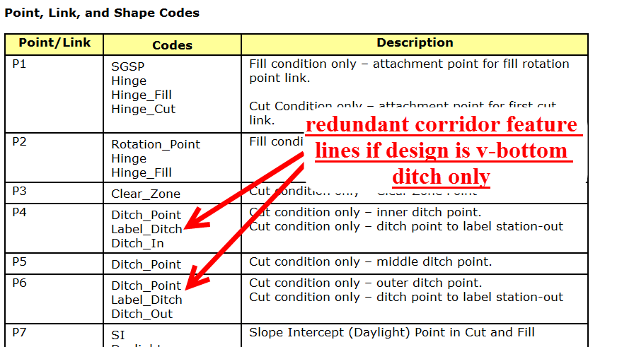
Turn off connection of unneeded corridor feature lines to improve system performance.
Some subassemblies produce corridor points which are assigned multiple point codes. When a corridor is constructed, by default a corridor feature line is created for each corridor point code. Corridor points with multiple codes produce multiple coincident corridor feature lines. The redundant corridor feature lines can be turned off by un-checking them in the Corridor Properties dialog box as shown below, only 1 corridor feature line per corridor point is needed to define surface models.