Urban design - centerline profile setup
Last updated: 2026-01-06
Total video time: 31:41
Exercise files: urbn-dsn-cntrln-prfl-setup-data-C3D14.zip
 Assembly
urbn-dsn-cntrln-prfl-setup-01.mp4 7:17
Urban design requires particular attention to impacts on adjacent properties. In this example, we will use a setup corridor to work from the outside (back of sidewalk) to the inside (roadway centerline).
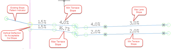
The assembly consists of generic subassemblies that form the roadway cross section. The baseline of the assembly falls at the outside edge of the sidewalk. Then, it builds inward toward the roadway centerline along two paths that represent the acceptable extremes for cross sectional slopes. The lower portion of the assembly, which represents the minimum roadway profile, includes a vertical link at the outside edge of the sidewalk. The designer can decide the magnitude of this vertical link. It represents an expected acceptable amount of cut slope behind the sidewalk to match into the adjacent property.
On the opposite side of the assembly baseline is a single LinkOffsetOnSurface subassembly. This subassembly will target the existing terrain at an offset chosen by the designer. Later on in the workflow, we will use the feature line created by this subassembly to provide information about existing drainage patterns.
Setup corridor
urbn-dsn-cntrln-prfl-setup-02.mp4 5:33
- Create a existing ground surface profile along the outside sidewalk alignment(s).
- Create a new corridor. Example name: Setup-96-Centerline Profile
- Alignment = outside sidewalk
- Profile = Existing surface profile from step 1
- Assembly = Centerline Profile Setup
- Target surface = Exist
- Set corridor region limits to the limits.
- Set frequency to something large (say 10,000) and set "At profile geometry points" to yes
- Add another baseline/region for the opposite side of the roadway outside sidewalk alignment and existing surface profile.
- Create four corridor surfaces using the corresponding links. Boundaries are not needed.
- Crdr-96-Setup-CenterlineProfile-MaxLt
- Crdr-96-Setup-CenterlineProfile-MinLt
- Crdr-96-Setup-CenterlineProfile-MaxRt
- Crdr-96-Setup-CenterlineProfile-MinRt
Setup surface profiles
urbn-dsn-cntrln-prfl-setup-03.mp4 7:12
- Create surface profiles for the centerline alignment on the four surfaces created in the previous section.
- Color code the surface profiles so the left side profiles are the same and the right side profiles are the same.
- Split the corridor regions to separate out intersection areas (approximate). Once separated, delete the intersection regions. Those gaps will appear in the surface profiles and indicate where the intersections are when creating the proposed centerline profile. Note: The max triangle distance for the surfaces may need to be reduced to for the gaps in the surfaces.
- If there is superelevation on the project, label the centerline alignment with the begin/end normal crown locations and the reverse crown locations. Split the corridor regions on the low side of the superelevation at the reverse crown locations. Split the corridor regions on the high side of the superelevation at the begin/end normal crown locations. The regions between the reverse crown locations (low side) and between the norm crown locations (high side) can be deleted. These areas will not be represented correctly by the setup corridor.
Slope patterns
urbn-dsn-cntrln-prfl-setup-04.mp4 4:51
The slope patterns feature of the corridor can be a useful design aid for determining existing drainage patterns. In this workflow, we will use the slope pattern feature to determine if the existing terrain is sloped toward the roadway or away from the roadway at any given location.
- Select the centerline profile setup corridor.
- Corridor contextual ribbon > Modify Corridor > Slope Patterns
- Add slope pattern
- Choose the Sdwk-Out-Max feature line. This is the upper feature line located at the outside of the sidewalk (corridor region baseline)
- Choose the test feature line. This is the feature line created by the LinkOffsetOnSurface subassembly. The offset for this subassembly can be chosen by the designer to get a good representation of the existing terrain.
- Corridor contextual ribbon > Modify Corridor > Slope Patterns
The resulting tic marks will indicated whether the terrain is sloping toward the road or away from the road.
Info: The WisDOT template does not contain custom slope pattern styles. The designer can modify the styles to fit their preference.
Proposed centerline profile
urbn-dsn-cntrln-prfl-setup-05.mp4 6:48
Using the information gathered from the centerline profile setup corridor, the proposed centerline profile can be developed. A quick way to develop the profile is to establish the tangents first using the profile layout tools. Once the tangents are placed, they can be joined using the ‘solve tangent intersection' option under the tangents menu in the profile layout tools. Then place free curves to fit the constraints.
Tip: It is helpful to create two viewports (one plan, one profile). Then turn on the station tracker, so the slope patterns can be observed while developing the proposed profile.
Info: Do not forget to assign each PVI the correct K-table category using the ‘select PVI' tools in the profile layout tools.