Modeling rural driveways
Last updated: 2026-01-20
Total video time: 1:51:43
Datasets
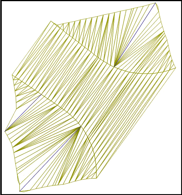
 Create combination surface of Top and Exist
crdr-ele-rurl-dwy-c3d24-01.mp4 6:47
Requirement: Reference FDM 15-5 Att. 3.1 for Project Folder Structures, Abbreviations, and File Naming Standards. The typical driveway design is detailed in Standard Detail Drawings 08D21 & 08D22.
- Unzip dataset trn-rurl-drvwys-c3d24-begin.zip to C:\Civil 3D Projects folder.
Info: If you don't have a Civil 3D Projects folder in C: drive, create one.
Open a new drawing file
- New function > Select Drawing dialog box > design-start.dwt > Open
- Rename file
- Menu > Save As > Save Drawing As dialog box
- Save in: browse to Civil 3D Projects\trn-rurl-drvwys-c3d24\dsgn\srfc folder.
- File name: type Srfc-Cmbn-Exist-Top
- Save
- Menu > Save As > Save Drawing As dialog box
Set data shortcuts
- Toolspace > Prospector tab > right-click Data Shortcuts > select Set Working Folder > Set Working Folder dialog box
- Browse to C:\Civil 3D Projects folder
- Select Folder
- Toolspace > Prospector tab > right-click Data Shortcuts > select Set Data Shortcuts Project Folder> Set Data Shortcuts Project Folder dialog box
- Double check trn-rurl-drvwys-c3d24 has green check mark.
- OK
Create Exist and Rfnt-All-Top surfaces
- Toolspace > Prospector tab > expand Data Shortcuts > expand Surface > right-click Exist > select Create Reference > Create Surface Reference dialog box
- Style: _No Display
- OK
- Toolspace > Prospector tab > expand Data Shortcuts > expand Surfaces > right-click Rfnt-All-Top > Create Reference > Create Surface Reference dialog box
- Style: _No Display
- OK
Combine Exist and Rfnt-All-Top surfaces
- Toolspace > Prospector tab > right-click Surfaces > select Create Surface > Create Surface Reference dialog box
- Name: Cmbn-Ex-TopThe file naming convention is important for the WisDOT Automated Targeting Tool to find its target.
- Style: ...
- Surface Style dialog box > dropdown > select EX BorderOK
- OK
Add Exist and Rfnt-All-Top surfaces
- Toolspace > Prospector tab > expand Surfaces > expand Cmbn-Ex-Top > expand Definition > right-click Edits > select Paste Surface > Select Surface to Paste dialog box
- Select Exist
- OK
- Toolspace > Prospector tab > expand Surfaces > expand Cmbn-Ex-Top > expand Definition > right-click Edits > select Paste Surface > Select Surface to Paste dialog box
- Select Rfnt-All-Top
- OK
- Quick Access > Save
Create data shortcuts
- Toolspace > Prospector tab > right-click Data Shortcuts > Create Data Shortcuts > Create Data Shortcuts dialog box
- Check box Cmbn-Ex-Top
- OK
We are done with this file. Select the "X" to close drawing.
Create driveway corridor file
crdr-ele-rurl-dwy-c3d24-02.mp4 4:22
Open a new drawing file
- New function > Select Drawing dialog box > design-start.dwt > Open
Tip: When you select the New function, it may open up Drawing2 for you instead of the Select Drawing dialog box.
- Rename file
- Menu > Save As > Save Drawing As dialog box
- Save in: browse to Civil 3D Projects\trn-rurl-drvwys-c3d24\dsgn\crdr folder.
- File name: type Crdr-Driveways
- Save
- Menu > Save As > Save Drawing As dialog box
Add Xrefs
- Add top surface
- Ribbon > WisDOT Design tab > Manage panel > Xref Tools dropdown > select Load Xref on Layer > Open dialog box
- In browse box, select trn-rurl-drvwys-c3d24 project folder
- Select base folder > select Topo-Ex.dwg
- Open
- Zoom Extents (ZE)to see its been added.
- Ribbon > WisDOT Design tab > Manage panel > Xref Tools dropdown > select Load Xref on Layer > Open dialog box
- Add data references of the surfaces
- Toolspace > Prospector tab > expand Data Shortcuts > expand Surfaces > right-click Cmbn-Ex-Top > select Create Reference > Create Reference dialog box
- Style: ...
- Surface Style dialog box > dropdown > select EX BorderOK
- OK
- Style: ...
- Toolspace > Prospector tab > expand Data Shortcuts > expand Surfaces > right-click Rfnt-All-Top > select Create Reference > Create Reference dialog box
- Style: ...
- Surface Style dialog box > dropdown > select Slope Intercept (No Plot)OK
- OK
- Style: ...
- Toolspace > Prospector tab > expand Data Shortcuts > expand Surfaces > right-click Cmbn-Ex-Top > select Create Reference > Create Reference dialog box
- Add data references of alignments
- Toolspace > Prospector tab > expand Data Shortcuts > expand Alignments > expand Centerline Alignments > right-click 25 > select Create Reference > Create Alignment Reference dialog box
- No changes
- OK
- Toolspace > Prospector tab > expand Data Shortcuts > expand Alignments > expand Offset Alignments > Shift + select all > right-click selection > select Create Reference
Info: All offset alignments selected include: 25-L-EGS, 25-L-EPS, 25-L-ETW, 25-R-EGS, 25-R-EPS, 25-R-ETW.
- Toolspace > Prospector tab > expand Data Shortcuts > expand Alignments > expand Centerline Alignments > right-click 25 > select Create Reference > Create Alignment Reference dialog box
Assign style to alignments
- Ribbon > WisDOT Design > Design panel > Alignment dropdown > select Assign Alignment Styles
- Select Style data file [Apply default, View default, browse Current, browse Last]: type AEnter
- Assign Alignment style [All, Select]: type AEnter
Quick Access > Save
Create driveway horizontal geometry
crdr-ele-rurl-dwy-c3d24-03.mp4 7:44
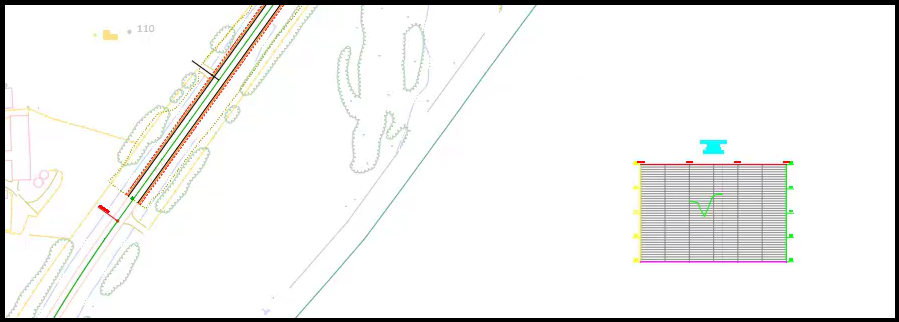
At the south end of our project is station number 370+00. Go north from that station to station 373+00 (3 minor station tick marks along centerline). To the left is a driveway. That is our focus for this part.
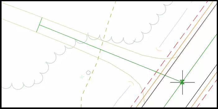
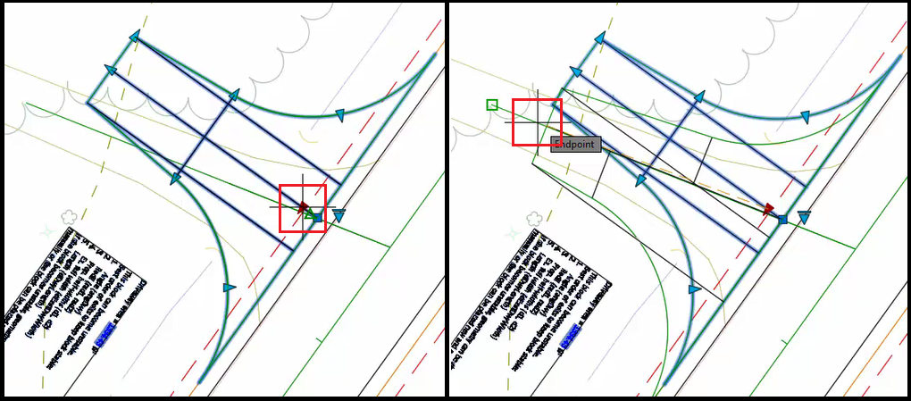
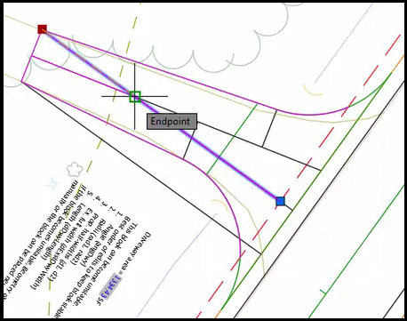
Find centerline of the driveway area
- Commandline: type LEnter
- Specify first point:Shift + right-click > menu > Endpoint OSnap Select south, back corner of driveway.
- Specify next point:Shift + right-click > menu > Perpendicular OSnap Select north side of driveway.
- Enter to end command.
- Commandline: type LEnter
- Specify first point:Shift + right-click > menu > Midpoint OSnap Select the line that was just created.
- Specify next point:Shift + right-click > menu > Perpendicular OSnap Select STH25 alignment.
- Enter to end command.
- Esc to deselect everything.
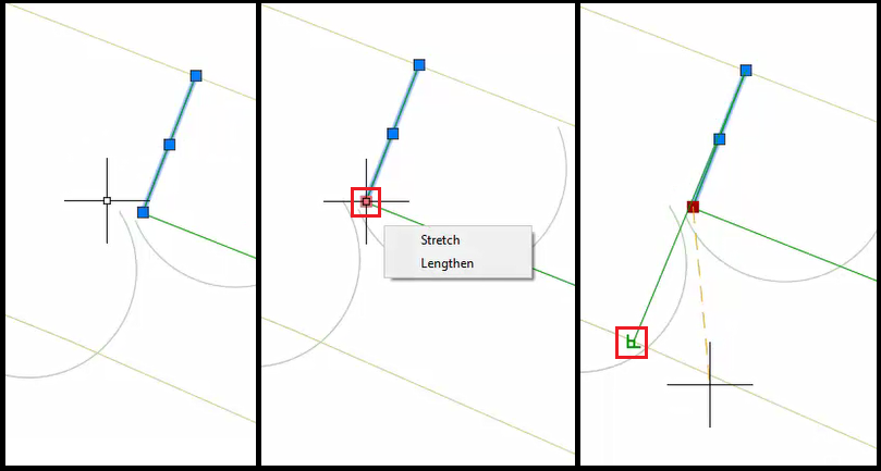
- At the back of the driveway, select the line that was used to create the midpoint and Delete.
- Select driveway centerline.
- Hover over the back endpoint and choose Lengthen.Drag endpoint past the Rfnt-All-Top surface line.
- Reverse the direction of driveway centerline.
- Ribbon > Home tab > Modify panel pulldown > select Reverse tool
Tip: Typing Reverse in Commandline will activate this tool.
- Select driveway centerline line.
- Ribbon > Home tab > Modify panel pulldown > select Reverse tool
- Enter to end command.
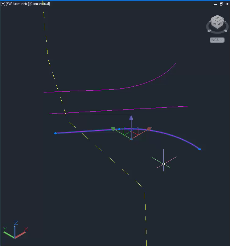
Create quick profile
With a profile view, user can view the distance and behavior of the surface to help determine what the slopes should be.
- Ribbon > Analyze tab > Ground Data panel > select Quick Profile tool
- Select driveway centerline.
- Create Quick Profile dialog box
- Uncheck Rfnt-All-Top
- OK
- Select an area outside of the project area to place the profile.
- Select "X" on panorama window to close it.
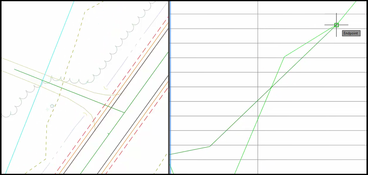
Measure grade
- Split Modelspace to show both driveway and profile close up.
- Ribbon > View tab > Model Viewports panel > select Viewport Configuration dropdown > select Two: Vertical
- On the left side, zoom in on driveway. On the right side, zoom in on profile.
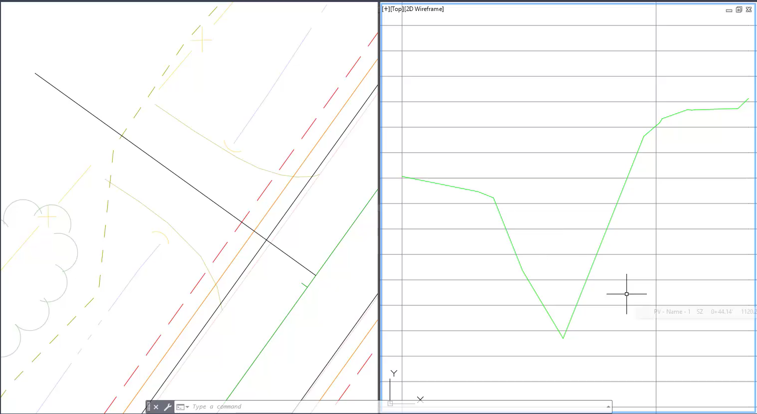
- Turn on station tracker.
- Select profile view to show grid.
- Context ribbon > Analyze panel > select Station Tracker dropdown > select All Viewports
Info: As you scroll across the quick profile view, a blue line moves across the driveway view.
- Esc to deselect the grid in quick profile view. The blue line still appears in driveway view.
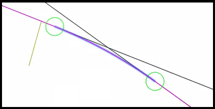
- Find the edge of gravel point in profile view, utilizing the blue line in the driveway view.
- Draw a line from edge of gravel shoulder to tie-in point.
- Commandline: type LEnter
- Specify first point:Shift + right-click > menu > Endpoint OSnap Select the edge of gravel point.
- Specify next point:Shift + right-click > menu > Endpoint OSnap Select a point outside the Rfnt-All-Top surface line, using the driveway view to help.
- Enter to end command.
Use inquiry tool to measure grade and tie-in point
- Context ribbon > Analyze tab > Inquiry panel > select Inquiry Tool
- Inquiry Tool palette
- Select an inquiry type: dropdown > expand Profile View > select Profile View Elevation and Grade between Points
Point 1: select Select from Screen

- Specify first profile view station and elevation point: With Endpoint OSnap on, in profile view, select edge of gravel point.
Point 2: select Select from Screen
- Specify second profile view station and elevation point: With Endpoint OSnap on, in profile view, select tie-in point
- Check Grade (Percentage)
Info: Leave palette open for future steps.
- Esc to deselect everything.
- Delete profile view.
- In right viewport, select profile grid and Delete , select slope grade line and Delete.
- Change the viewport to single view.
- Select left viewport to be active.
- Ribbon > View tab > Model Viewports panel > select Viewport Configuration dropdown > select Single
Quick Access > Save
Placing the dynamic driveway block
crdr-ele-rurl-dwy-c3d24-04.mp4 7:30
- Set the layer
- Ribbon > Home tab > Layers panel > select Layer Dropdown > scroll and select P_DWY
- Add driveway block using WisDOT templates.
- Ribbon > Home tab > Manage panel > Palette toggle to open the Tool Palette.
- Ribbon > WisDOT Design tab > Design Palettes panel > Parametric Blocks dropdown > select Rural Driveway Blocks
- Tool Palette > Rural Driveway tab > select Rurl-Dwy-Tan
- Shift+right-click > menu > Apparent Intersect OSnap to 25-L-EPS where it crosses the driveway center reference line.
- Rotate block
- Right-click origin grip point > menu > select Rotate
- Shift+right-click > menu > Nearest OSnap to 25-L-EPS.
- X to close Tool Palette.
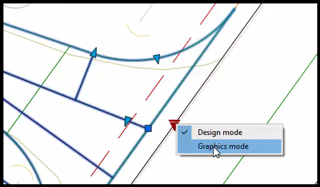
- With block selected, right-click on down arrow > menu > select Design mode
- With block selected, right-click > menu > Properties opens Properties palette.
- In Properties palette, scroll to the bottom to Custom fields.
- rad1: change to 20Enter
- rad2: change to 20Enter
- d1: change to 8Enter
- d2: change to 8Enter
- dExstDwyWidth: change to 17Enter
- In Properties palette, scroll to the bottom to Custom fields.
- Esc to deselect block.
- Reset the length of the driveway to measure from the centerline of STH 25 alignment.
- Commandline: type L
- Specify first point:Shift + right-click > menu > Endpoint OSnap snap to the point on STH 25.
- Specify next point:Shift + right-click > menu > Endpoint OSnap DON'T SNAP but hover over the endpoint at the end of the driveway until it reads Endpoint. Now type 51Enter
- Enter to end command.
- Esc to deselect object.
- Select old centerline and Delete.
- Select the block > Selection cycling > select Block Reference
- At the back end of driveway, select centerline arrow and drag down to the 51' point. Use Endpoint OSnap to snap to the point.
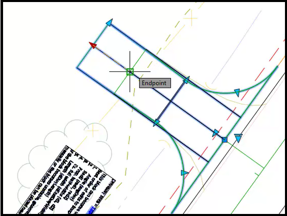
- Esc to deselect block.
- Now the centerline is no longer needed, select it and Delete.
- Quick Access > Save
- X to close Inquiry tool.
- X to close Properties palette.
Change driveway block into feature lines
crdr-ele-rurl-dwy-c3d24-05.mp4 8:38
Extract geometry from driveway block
- Commandline: type NCOPYEnter
- Select nested objects to copy or [Settings]: Select south outside edge of driveway block and driveway center reference line.
- Hit Enter 3 times.
- The south outside edge of driveway block is a polyline and driveway center reference line is a line.
Trim lines to edge of gravel shouler, 25-L-EGS
- Commandline: type TRIMEnter
- [cuTting edges, Crossing, mOde, Project, eRase]: type TEnter
- Select objects or <select all>: select 25-L-EGSEnter
- TRIM: select outside edge of driveway polyline between EGS and EPS > Selection cycling > select Polyline, select driveway center reference line between EGS and EPS > Selection cycling > select Line.
- Enter to end selection.
- Esc to deselect everything.
Create feature lines from objects
- Ribbon > Home tab > Create Design panel > Feature Line dropdown > select Create Feature Lines from Objects
- Select lines, arcs, polylines, or 3D objects to convert to feature lines: Select the outside edge of driveway polyline > Selection cycling > select Polyline and select driveway center reference line > Selection cycling > select Line.
- Enter to end selection.
- Create Feature Lines dialog box
- Site: select Create New Site button
- Site Properties - Site dialog box
- Information tab > Name: type Dwy 373+00 LT
- OK
- Site Properties - Site dialog box
- Check box Name and select Naming Template button
- Name Template dialog box
- Name: type Dwy, then check that the Property field says Next Counter and select Insert. The name should read Dwy <[Next Counter]>.
- Starting number: 1
- OK
- Name Template dialog box
- Check box Style and select WisDOT Standard
- Layer: select the Layer Selection button
- Object Layer dialog box
- Base Layer Name: select Layer Selection button
- Layer Selection dialog box
- Scroll and select P_DWY
- OK
- Layer Selection dialog box
- Modifier: select Suffix
- Modifier value: type -* (dash+asterisk)
- OK
- Base Layer Name: select Layer Selection button
- Object Layer dialog box
- Check box Erase existing entities
- Check box Assign elevations
- OK
- Site: select Create New Site button
- Assign Elevations dialog box
- Select radio From surface, surface name Cmbn-Ex-Top.
- Uncheck box Insert intermediate grade break points.
- Uncheck box Relative elevation to surface.
- OK
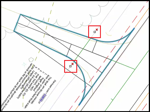
Assign elevations to feature lines
- Select outside edge driveway feature line > Selection cycling > select Feature Line
- Context ribbon > Edit Elevations panel > select Set Grade /Slope between Points tool

Info: If the Edit Elevations panel is not available, go to the Modify panel and select Edit Elevations.
- Specify the start point: Starting on the south side of driveway, select point at EGS.
- Specify elevation:Enter
- Specify the end point: select point at tie-in at back of driveway.
- Specify grade:Enter
- Select outside edge driveway feature line > Selection cycling > select Feature Line
- Specify the start point: Starting on the north side of driveway, select point at EGS.
- Specify elevation:Enter
- Specify the end point: select point at tie-in at back of driveway.
- Specify grade:Enter
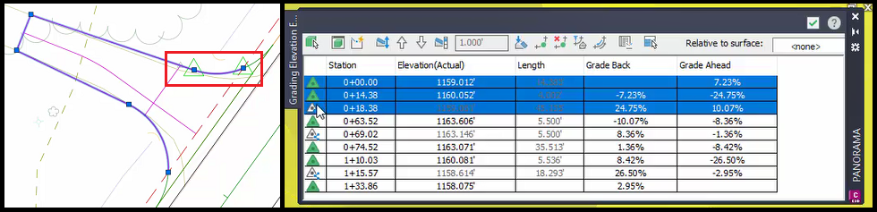
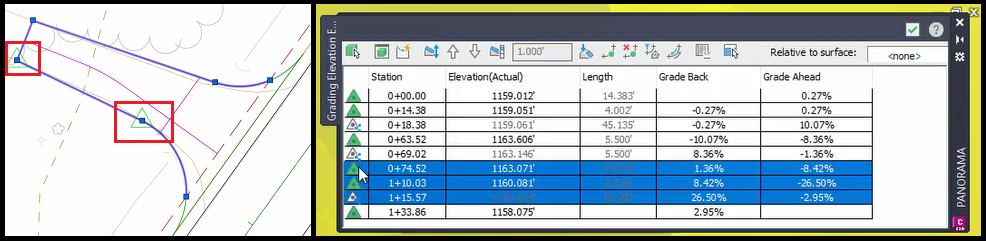
- Spot check elevations in elevation editor
- Select feature line.
- Context ribbon > Edit Elevations panel > select Elevation Editor tool
- green check mark to close Elevation Editor panorama when done.
- Esc to deselect object.
Quick Access > Save
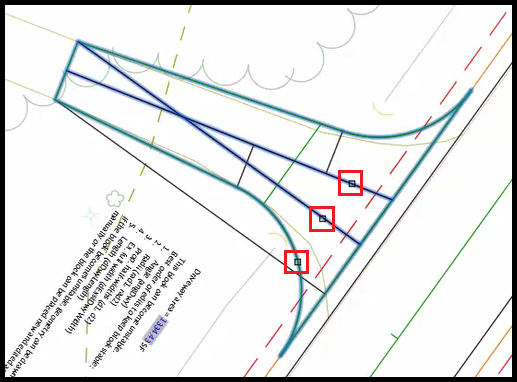
Break driveway edge feature lines
- With block selected, right-click on down arrow > menu > select Graphics mode
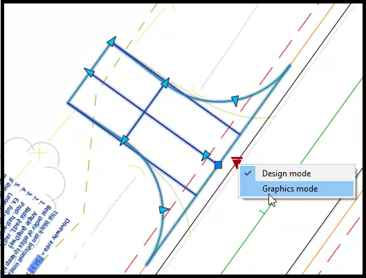
- Esc to deselect block.
- Select driveway edge feature line > Selection cycling > select Feature Line
- Context ribbon > Edit Geometry panel > select Break tool

Info: If the Edit Geometry panel is not available, go to the Modify panel and select Edit Geometry.
- Select an object to break: Select back edge of driveway feature line > Selection cycling > Feature Line.
- Specify second break point: Using Endpoint OSnaps, select north corner point of feature line.
- Esc to deselect object.
- Select the other part of the feature line.
- Context ribbon > Edit Geometry panel > select Delete PI tool
- Specify point: select the endpoint of feature line (near centerline).
- Enter to end selection.
- When finished, there should be 3 feature lines; left of driveway edge, center reference line, and right of driveway edge.
Create driveway assembly
crdr-ele-rurl-dwy-c3d24-06.mp4 5:19
Requirement: Reference FDM 15-5 Att. 3.2 for WisDOT Naming Standards.
Rename feature lines
For naming, we set our vantage point from the road looking up the driveway (north=right, south=left).
- Select right driveway edge feature line > selection cycling > select Feature Line
- Right-click > menu > select Properties
- Properties palette
- Name: Dwy RT Edge 01Enter
- Esc to deselect feature line.
- Select left driveway edge feature line > selection cycling > select Feature Line
- Properties palette
- Name: Dwy LT Edge 01Enter
- Esc to deselect feature line.
- Select driveway center reference line > selection cycling > select Feature Line
- Properties palette
- Name: Dwy RL 373+00 LTEnter
- Esc to deselect feature line.
- Quick Access > Save
- X to close Properties palette
Create assembly
- Ribbon > WisDOT Design tab > Design Palettes panel > select WisDOT Subassemblies
- WisDOT Subassemblies tool palette > Entrance-Assemblies tab > Rural Driveway > select Rural Driveway assembly
- Specify location for assembly: select an open area outside drawing.
- Esc to end selection.
- X to close tool palette.
Setting up viewport views
crdr-ele-rurl-dwy-c3d24-07.mp4 5:57
Adding a second, isometric view can help with analyzing your design and troubleshoot.
Setting up viewport views
- Ribbon > View tab > Model Viewports panel > Viewport Configuration dropdown > select Two: Vertical
- Left Viewport:
- Set left side to be top-down view of driveway.
- Right Viewport:
- Set the right side to the isometric view.
- Select right side so it is active.
- At the top of viewport, look for the In-Canvas tools, select 2D Wireframe and change it to Conceptual.
- Select the left driveway edge feature line.
- Go to the View Cube and select the SW corner. It will orbit to the isometric view and zoom to the feature line selected.

- Esc to deselect feature line.
- Change the Cmbn-Ex-Top surface style.
- Toolspace > Prospector tab > expand Surfaces > right-click Cmbn-Ex-Top > select Surface Properties > Surface Properties dialog box
- Surface style > dropdown > select Top Border
- OK
- Toolspace > Prospector tab > expand Surfaces > right-click Cmbn-Ex-Top > select Surface Properties > Surface Properties dialog box
Saving views
- Select right viewport
- Ribbon > View tab > Name Views panel > select New View > New View dialog box
- View Name: type 3D-Dwy 373+00 LT
- Boundary: Current Display
- Uncheck box Save Layer Snapshot with View
- OK
- Ribbon > View tab > Name Views panel > select New View > New View dialog box
- Select left viewport
- Ribbon > View tab > Name Views panel > select New View > New View dialog box
- View Name: type Top-Dwy 373+00 LT
- Boundary: Current Display
- Uncheck box Save Layer Snapshot with View
- OK
Tip: To find these view again, go to the Ribbon > View tab > Named Views panel > select the View dropdown and they will be listed there.
- Ribbon > View tab > Name Views panel > select New View > New View dialog box
Quick Access > Save
Create driveway corridor
crdr-ele-rurl-dwy-c3d24-08.mp4 7:37
Create corridors
- Ribbon > Home tab > Create Design panel > Corridor dropdown > select Corridor > Create Corridor dialog box
- Name: DWY
- Feature lines area
- Feature Line: In the first field, double-click for dropdown menu, and select Dwy RL 373+00 LT.
- Assembly: In the first field, double-click for dropdown menu, and select RuralDwy.
- Target Surface: dropdown > select Cmbn-Ex-Top
- OK
- Baseline and Region Parameters dialog box
- In row RG - RuralDwy > Frequency column: select ... > Frequency to Apply Assemblies dialog box
- Horizontal Baseline > Along tangents: 1.000'
- Horizontal Baseline > Curve increment: 1.000'
- Horizontal Baseline > Along spirals: 1.000'
- Vertical Baseline > Along vertical curves: 1.000'
- Anything with a Yes/No option: set to Yes.
- OK
- OK
- In row RG - RuralDwy > Frequency column: select ... > Frequency to Apply Assemblies dialog box
- Alert: The corridor definition has been modified and needs to be rebuilt. What do you want to do? Select Rebuild the corridor.
Assign targets to corridors
- Ribbon > WisDOT Design tab > Design panel > Corridor dropdown > select Assign Corridor Targets > Assign Corridor Targets dialog box
- Corridor: DWY
- Baseline: DWY RL 373+00 LT
- Region: automatically assigned
- Targets:
- Righthand dropdown menu: select Crdr-Trgt-Assgn-Dwy.csv
- Select Open Template to open CrdrTrgtAssgn-Dwy spreadsheet
- Save a copy of this in project folder
- File > Save As > Browse > Save As dialog box
- Select (single click) the file CrdrTrgtAssgn-Dwy.csv. This will copy the name into File name location.
- Browse to project folder, C:\Civil 3D Projects\trn-rurl-drvwys-c3d24\dsgn\crdr
- Save
- X to close spreadsheet.
- File > Save As > Browse > Save As dialog box
- Select radio Assign
- select Folder icon > Select Corridor Targets Data File dialog box
- This should open to the crdr folder, select file CrdrTrgtAssgn-Dwy.csv.
- Open
- select Folder icon > Select Corridor Targets Data File dialog box
- Check box Rebuild Corridor
- OK
- Process Complete.
- Close
Adding surface to the corridor
crdr-ele-rurl-dwy-c3d24-09.mp4 6:23
Add surface
- Ribbon > WisDOT Design tab > Design panel > Corridor dropdown > select Create Corridor Surfaces
- Select Corridor Surface definition file [Apply default, View default, browse Current, browse Last]: type AEnter
- Select Corridor: select corridor.
- Alert: Create Corridor Surfaces: Process Complete. Rebuild Corridor? Yes
- Delete the Crdr-DWY-Datum surface.
- Select corridor > right-click menu > select Corridor Properties > Corridor Properties dialog box
- Surface tab > select Crdr-DWY-Datum and the Red X to delete.
- OK
- Select corridor > right-click menu > select Corridor Properties > Corridor Properties dialog box
- Ribbon > WisDOT Design tab > Design panel > Corridor dropdown > select Shrink Wrap Corridor Surface > Shrink Wrap Corridor Surface dialog box
- Select Select By Surface Definition.
- Daylight EGS highlights.
- OK
- Review corridor.
- Close
Edit surface style
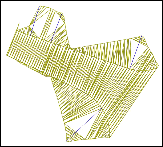
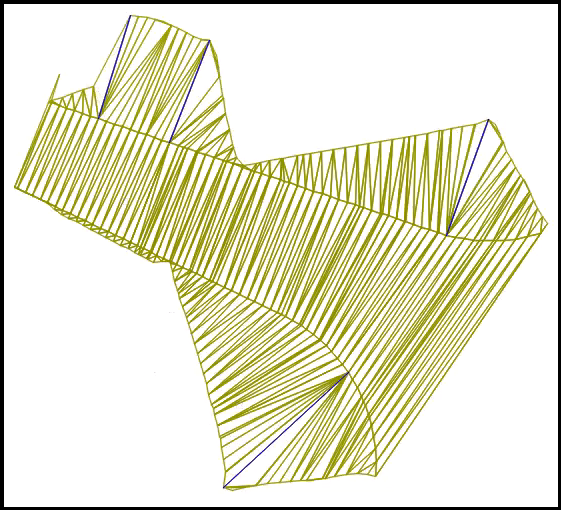
There are some open flat triangles where the surface triangles went across instead of towards the driveway.
- Change surface style to triangles.
- Select the corridor.
- Toolspeace > Prospector tab > expand Surfaces > right-click Crdr-Dwy_Top > select Surface Properties > Surface Properties dialog box
- Information tab > Default styles > Surface Styles dropdown > select Top Triangles
- OK
Review tie-in points
-
Select corridor by selecting a frequency line.
-
Context ribbon > Modify Corridor Sections panel > select Selection Editor
-
Context ribbon > Station Selection panel > select Go to First Station button
 .
. -
Review tie-in.
-
Context ribbon > Station Selection panel > select Go to Last Station button
 .
. -
Review tie-in.
-
Context ribbon > Close panel > select Close
Quick Access > Save
Create Data Shortcut
- Toolspace > Prospector tab > right-click Data Shortcuts > select Create Data Shortcut > Create Data Shortcuts dialog box
- Select check box Surfaces, including Crdr-Dwy-Top
- OK
Driveway with skewed alignment and changing vertical slopes, Part 1
crdr-ele-rurl-dwy-c3d24-10.mp4 10:33
- Change viewport to single view.
- Select left viewport to be active.
- Ribbon > View tab > Model Viewports panel > Viewport Configuration dropdown > select Single
Zoom and pan to station number 392+00. To the left is a driveway. That is our focus for this part.
Create a quick profile
- Starting at the back end of driveway, draw a line to create a midpoint for centerline.
- Commandline: type LEnter
- Specify first point:Shift + right-click > Nearest OSnap > select south edge of driveway (inside the treeline)
- Specify next point:Shift + right-click > Perpendicular OSnap > select north edge of driveway
- Right-click menu > Enter
- Draw a driveway centerline.
- Commandline: type LEnter
- Specify first point:Shift + right-click > Midpoint OSnap > select the new line
- Specify next point:Shift + right-click > Nearest OSnap > select STH 25 centerline alignment
Tip: Remembering there is a curve, keep the centerline center when tying into roadway, not perpendicular.
- The line at the back end of driveway is no longer needed. Select and Delete.
- Reverse the direction of the driveway centerline.
- Commandline: type REVERSEEnter
- Select Object: select driveway centerlineEnter
- Create a quick profile
- Ribbon > Analyze tab > Ground Data panel > select Quick Profile tool
- Select object: select driveway centerline.
- Create Quick Profiles dialog box
- In Selected Column, only have Crdr-Ex-Top checked.
- OK
- Select profile view origin: select an open area in the drawing.
- Close panorama window, for more visual space.
- Change viewport to two views.
- Ribbon > View tab > Model Viewports panel > Viewport Configuration dropdown > select Two: Vertical
- The left viewport zoom to driveway.
- The right viewport zoom to profile.
Create temporary profile with a landing and use inquiry tool to view slope grades
- In the profile view, create a 15' landing off EGS.
- Commandline: type LEnter
- Specify first point:Shift + right-click > Endpoint OSnap > select point at EGS
- (Transparent command) Commandline: type 'pgl (profile grade length) Enter
- Select a profile view: select on profile grid.
- Specify grade: type 2Enter
- Specify length: type 15Enter
- Escto resume line command.
- Specify next point: select a point past the Rfnt-All-Top.
- Enter to end command.
- Use inquiry tool to view slope grades.
- Ribbon > Analyze tab > Inquiry panel > select Inquiry Tool
- Inquiry Tool palette
- Profile View Name: select ...
- Select Profile View dialog box
- Select PV - Name - 2
- OK
- Select Profile View dialog box
Point 1: select Select from Screen
- Specify first profile view station and elevation point: Endpoint OSnap to the bend of the slope.
Point 2: select Select from Screen
- Specify second profile view station and elevation point: Endpoint OSnap to the point at back end of profile.
- Profile View Name: select ...
- Enter to end command.
- Delete profile view.
- In right viewport, select profile grid and Delete , select slope grade line and Delete.
- Change the viewport to single view.
- Select left viewport to be active.
- Ribbon > View tab > Model Viewports panel > select Viewport Configuration dropdown > select Single
Create a line that goes from roadway to the actual tie-in point at the end of the driveway
- Commandline: type LEnter
- Specify first point:Shift + right-click > Endpoint OSnap > select point at STH 25 centerline
- Specify next point:Shift + right-click > menu > Endpoint OSnap DON'T SNAP but hover over the endpoint at the end of the driveway until it reads Endpoint. Now type 77Enter
Info: The measurement of 77' can be found in the Inquiry Tool palette, Point 2 Station value.
- Enter to end command.
- Esc to deselect object.
- Select original driveway centerline and Delete.
Create a temporary line to correct midpoint and center driveway centerline
- Commandline: type LEnter
- Specify first point:Shift + right-click > Endpoint OSnap > select point at the end of driveway centerline
- Specify next point:Shift + right-click > Perpendicular OSnap > select the north side of driveway
- Right-click menu > Enter
- Select line.
- Grab the point at the midpoint of the tie-in line.
- Specify next point:Shift + right-click > Perpendicular OSnap > select the south side of driveway
- Esc to end command.
- Connect driveway centerline endpoint to the midpoint of tie-in line.
- Zoom in to the midpoint.
- Select the driveway centerline endpoint and stretch
- Specify stretch point:Shift + right-click > Midpoint OSnap > select the tie-in line
- Esc to end command.
- The tie-in line is no longer needed. Select the line and Delete.
Create a temporary line to indicate where the bend is in the driveway
- Commandline: type LEnter
- Specify first point:Shift + right-click > Endpoint OSnap > select point at STH 25 alignment
- Specify next point:Shift + right-click > menu > Endpoint OSnap DON'T SNAP but hover over the endpoint at the end of the driveway until it reads Endpoint. Now type 34Enter
Info: The measurement of 34' can be found in the Inquiry Tool palette, Point 1 Station value.
- Enter to end command.
- X to close Inquiry Tool palette.
Driveway with skewed alignment and changing vertical slopes, Part 2
crdr-ele-rurl-dwy-c3d24-11.mp4 6:59
Add driveway block using WisDOT templates
- Ribbon > WisDOT Design tab > Manage panel > select Palettes button
- Ribbon > WisDOT Design tab > Design Palettes panel > Parametric Blocks dropdown > select Rural Driveway Blocks
- Tool Palette > Rural Driveway tab > select Rurl-Dwy-Tan
- Specify insertion point or [Base, Scale, Rotate]: Using Apparent Intersect OSnap, select point at the intersection of driveway centerline and 25-L-EPS alignment.
Adjust driveway placement
- Right-click origin grip point > menu > select Rotate
- Shift+right-click > menu > Nearest OSnap to 25-L-EPS alignment.
- X to close Tool palette.
Edit driveway properties
- With block selected, right-click on down arrow > menu > select Design mode
- With block selected, right-click > menu > Properties opens Properties palette.
- In Properties palette, scroll to the bottom to Custom fields.
- The first step is to adjust the angDwy value, but since the driveway is at a different angle, use the block's grip points to adjust the angle.
- Select the driveway block.
- Select arrow grip point nearest to origin point, Endpoint OSnap to the driveway centerline.
- The angDwy value has changed.
- rad1: change to 20Enter
- rad2: change to 20Enter
- d1: change to 8Enter
- d2: change to 8Enter
- dExstDwyWidth: change to 11Enter
- The first step is to adjust the angDwy value, but since the driveway is at a different angle, use the block's grip points to adjust the angle.
- Adjust the length of the driveway.
- Select the arrow grip point at the back end of driveway block and Endpoint OSnap to the 77' line.
- Esc to deselect the object.
- The 77' line is no longer needed.
- Select line > Selection cycling > select Line and Delete.
Create an offset alignment using the 34' landing line
Since the 34' line isn't at a right angle to STH 25 centerline alignment, it has to be offset to the end of the 34' line.
- Commandline: type OFFSETEnter
- Specify offset distance or [Through, Erase, Layer]: type TEnter
- Specify object of offset: select STH 25 centerline
- Specify through point or [Exit, Multiple, Undo]: Endpoint OSnap to the endpoint of 34' line.
- Esc to end command.
Trim offset alignment to the driveway edges
- Commandline: type TRIMEnter
- [cuTting edges, Crossing, mOde, Project, eRase]: type TEnter
- Select objects or [select all]: select driveway outside edge lineEnter
- Select objects: select offset line outside south outside driveway edge and north outside driveway edge, keeping the line inside the driveway block.
- Esc to deselect object.
- The 34' landing line is no longer needed. Select it and Delete.
Extract the driveway edge, driveway reference line, and centerline
- Commandline: type NCOPYEnter
- Select nested objects to copy: select the driveway edge, driveway reference line, and centerline.
- Hit Enter 3 times.
- Commandline: type TRIMEnter
- [cuTting edges, Crossing, mOde, Project, eRase]: type TEnter
- Select objects or [select all]: select 25-L-EGS alignmentEnter
- TRIM: select outside edge of driveway polyline between EGS and EPS > Selection cycling > select Polyline, select driveway reference line between EGS and EPS > Selection cycling > select Line, select centerline between EGS and EPS > Selection cycling > select Line.
- Enter to end selection.
- Esc to deselect everything.
Driveway with skewed alignment and changing vertical slopes, Part 3
crdr-ele-rurl-dwy-c3d24-12.mp4 8:23
Create feature lines
- Ribbon > Home tab > Create Design panel > Feature Line dropdown > Create Feature Lines from Objects
- Select lines, arcs, polylines, or 3D polylines to convert to feature line: select driveway edge > Selection cycling > Polyline, select driveway reference line > Selection Cycling > Line, and select centerline > Selection cycling > Line.
- Enter to end selection.
- Create Feature Lines dialog box
- Site: select Create New Sitebutton
- Site Properties - Site dialog box
- Information tab > Name: type DWY 392+00 LT
- OK
- Site Properties - Site dialog box
- Check box Name and select Naming Template button
- Name Template dialog box
- Name: type Dwy, then check that the Property field says Next Counter and select Insert. The name should read Dwy <[Next Counter]>
- Starting number: 1
- OK
- Name Template dialog box
- Check box Style and select WisDOT Standard
- Layer: select the Layer Selection button
- Object Layer dialog box
- Base Layer Name: select Layer Selection button
- Layer Selection dialog box
- Scroll and select P_DWY
- OK
- Layer Selection dialog box
- Modifier: select Suffix
- Modifier value: type -* (dash+asterisk)
- OK
- Base Layer Name: select Layer Selection button
- Object Layer dialog box
- Check box Erase existing entities
- Check box Assign elevations
- OK
- Site: select Create New Sitebutton
- Assign Elevations dialog box
- Select radio From surface, surface name Cmbn-Ex-Top.
- Uncheck box Insert intermediate grade break points.
- Uncheck box Relative elevation to surface.
- OK
Join and create a curve where driveway reference line and centerline meet
- Select centerline > Selection cycling > Feature Line
- Select grip point near roadway > Shift + right click > menu > Apparent Intersect OSnap and drag to the intersection point of the two lines.
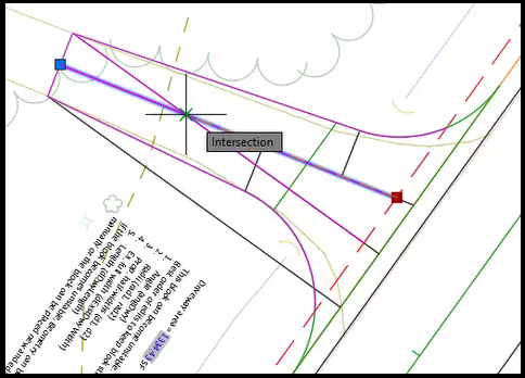
- Esc to deselect object.
- Select driveway reference line > Selection cycling > Feature Line
- Select grip point near roadway > Shift + right click > menu > Endpoint OSnap and drag to the intersection point of the two lines.
- Esc to deselect object.
- Use Fillet command to create curve
- Select driveway reference line near the roadway > Selection cycling > Feature Line
Ribbon > Home tab > Edit Geometry panel > select Fillet tool

- Specify corner or [All Join Radius]: type REnter
- Specify radius: type 25Enter
- Specify corner or [All Join Radius]: type JEnter
- Select connecting feature line, polyline, or 3D polyline: Select centerline near the back end of driveway > Selection cycling > Feature Line.
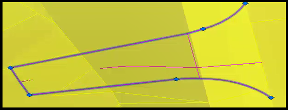
- Edit curve.
Ribbon > Home tab > Edit Geometry panel > select Edit Curve tool

- Select feature line curve to edit or [Delete]: Zoom in and select the curve.
- Edit Feature Line Curve dialog box
- Radius: type 50
- OK
- Esc to end command.
Info: If you look at the curve feature line, circle grips represent the 25' radius curve and square grips represent the 50' radius curve.
- Esc to deselect object.
Quick Access > Save
Change viewport views and settings
- X to close Properties palette.
- Change Visualization mode.
- Select driveway block, right-click on down arrow > menu > select Graphics mode
- Select driveway block, right-click on down arrow > menu > select Graphics mode
- Set up viewport views
- Ribbon > View tab > Model Viewports panel > select Viewport Configuration dropdown > select Two: Vertical
- Left Viewport:
- Set left side to be top-down view of driveway.
- Right Viewport:
- Select right side so it is active.
- At the top of viewport, look for the In-Canvas tools, select 2D Wireframe and change it to Conceptual.
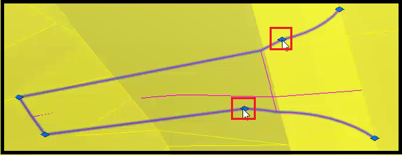
- Select driveway edge feature line > Selection cycling > Feature Line.
- Go to the View Cube and select the SW corner. It will orbit to the isometric view and zoom to the feature line selected.
- Save viewport views
- Select right viewport
- Ribbon > View tab > Name Views panel > select New View > New View dialog box
- View Name: type 3D-Dwy 392+00 LT
- Boundary: Current Display
- Uncheck box Save Layer Snapshot with View
- OK
- Ribbon > View tab > Name Views panel > select New View > New View dialog box
- Select left viewport
- Ribbon > View tab > Name Views panel > select New View > New View dialog box
- View Name: type Top-Dwy 392+00 LT
- Boundary: Current Display
- Uncheck box Save Layer Snapshot with View
- OK
- Ribbon > View tab > Name Views panel > select New View > New View dialog box
- Select right viewport
Driveway with skewed alignment and changing vertical slopes, Part 4
crdr-ele-rurl-dwy-c3d24-13.mp4 7:37
Correct feature lines that fall below the Cmbn-Ex-Top surface
- Edit driveway feature lines.
- Select driveway edge feature line > Selection cycling > select Feature Line
- Context ribbon > Edit Elevations panel > select Set Grade/Slope between Points tool
Info: If the Edit Elevations panel is not available, go to the Modify panel and select Edit Elevations.
- Specify the start point: At the north side of driveway, select point at EGS.
- Specify elevation:Enter to accept.
- Specify the end point: Select point at back end of driveway.
- Specify grade or [Slope Elevation Difference]:Enter to accept.
- Select object: Select driveway edge feature line > Selection cycling > select Feature Line
- Specify the start point: At the south side of driveway, select point at EGS.
- Specify elevation:Enter to accept.
- Specify the end point: Select point at back end of driveway.
- Specify grade or [Slope Elevation Difference]:Enter to accept.
- Enter to end command.
- Esc to deselect object.
- Edit driveway centerline.
- Select driveway centerline
- Context ribbon > Edit Elevations panel > select Set Grade/Slope between Points tool
- Specify the start point: Select point at EGS.
- Specify elevation:Enter to accept.
- Specify the end point: Select point at back end of driveway.
- Specify grade or [Slope Elevation Difference]:Enter to accept.
- Enter to end command.
- Esc to deselect object.
- Review grades and elevations.
- Select driveway edge feature line > Selection cycling > select Feature Line
- Context ribbon > Edit Elevations panel > select Elevation Editor
- Review grades and elevations.
Tip: Select the Select from Screen button
to select specific lines to review. - Select green check mark to close panorama.
Quick Access > Save
Change breakline into feature line
- Select polyline.
- Ribbon > Home tab > Create Design panel > Feature Line dropdown > select Create Feature Line from Objects
- Select lines, arcs, polylines, or 3D objects to convert to feature lines: select polyline.
- Right-click menu > Enter
- Create Feature Lines dialog box
- Site: Dwy 392+00 LT
- Name: type Dwy 392+00 LT Break
- Check box Style and select WisDOT Standard
- Layer: select the Layer Selection button
- Object Layer dialog box
- Base Layer Name: select Layer Selection button
- Layer Selection dialog box
- Scroll and select P_DWY
- OK
- Layer Selection dialog box
- Modifier: select Suffix
- Modifier value: type -* (dash+asterisk)
- OK
- Base Layer Name: select Layer Selection button
- Object Layer dialog box
- Check box Erase existing entities
- Uncheck Assign elevations and Weed points
- OK
Info: Notice that the breakline doesn't have a known elevation and caused all tie-in feature lines to go to 0 (zero) elevation.
Correct elevations by adding EGS feature line and using an elevation reference tool
Since the EGS alignment has a known elevation, this will the correct the elevation issue.
- Ribbon > Home tab > Create Design panel > Feature Line dropdown > select Create Feature Line > Create Feature Line dialog box
- Don't change anything. Select OK.
- Specify start point: Endpoint OSnap at the point where south driveway edge feature line meets EGS.
- Specify elevation or [Surface]:Enter to accept.
- Specify the next point: Endpoint OSnap at the point where north driveway edge feature line meets EGS.
- Specify grade or [Slope Elevation Difference]: type EEnter
- Specify elevation or [Grade SLope Difference SUrface Transition]:Enter to accept.
- Enter to end command.
- Select EGS feature line > Selection cycling > Feature Line.
- Context ribbon > Edit Elevations panel > select Adjacent Elevations by Reference tool

- Select object to edit or [Name]: select breakline feature line.
- Specify elevation difference or [Grade Slope]: type GEnter
- Specify grade of [Slope Difference]: type 2Enter
- Esc to end command.
- Esc to deselect.
- The EGS feature line is no longer needed. Select EGS feature line > Selection cycling > Feature Line and Delete.
Quick Access > Save
Driveway with skewed alignment and changing vertical slopes, Part 5
crdr-ele-rurl-dwy-c3d24-14.mp4 5:40
Edit transitions to breakline along driveway edge lines
- Both the north and south driveway edge feature lines are not smooth. The grades need to be adjusted.
- Select driveway edge feature line > Selection cycling > select Feature Line
- Context ribbon > Edit Elevations panel > select Elevation Editor
- In the Elevation Editor, as you select on a triangle, the corresponding triangle will appear on the drawing at its location. The first 3 are for the points along north driveway edge between EGS and breakline. Shift + select all 3 rows.
-
Select Flatten Grade or Elevation button

- Flatten dialog box
- Select radio Constant Grade
- OK
- Flatten dialog box
- Rows 6 - 8 are along the south driveway edge between breakline and back end of driveway. Shift + select all 3 rows.
-
Select Flatten Grade or Elevation button
- Flatten dialog box
- Select radio Constant Grade
- OK
- Review all values in Elevation Editor panorama.
- Select green check mark to close panorama.
Quick Access > Save
Break driveway edge feature lines
- Select driveway edge feature line > Selection cycling > select Feature Line
- Context ribbon > Edit Geometry panel > select Break tool
Info: If the Edit Geometry panel is not available, go to the Modify panel and select Edit Geometry.
- Select an object to break: Select back edge of driveway feature line > Selection cycling > Feature Line.
- Specify second break point: Using Endpoint OSnaps, select north corner point of feature line.
- Esc to deselect object.
- Select the south driveway edge feature line.
- Context ribbon > Edit Geometry panel > select Delete PI tool
- Specify point: select the endpoint of feature line (near centerline).
- Enter to end selection.
When finished, there should be 4 feature lines; left of driveway edge, center reference line, right of driveway edge, and middle breakline.
Rename the feature lines
For naming, we set our vantage point from the road looking up the driveway (north=right, south=left).
- Select right driveway edge feature line > selection cycling > select Feature Line
- Right-click > menu > select Properties
- Properties palette
- Name: Dwy RT Edge 02Enter
- Esc to deselect feature line.
- Select left driveway edge feature line > selection cycling > select Feature Line
- Properties palette
- Name: Dwy LT Edge 02Enter
- Esc to deselect feature line.
- Select center reference line > selection cycling > select Feature Line
- Properties palette
- Name: Dwy RL 392+00 LTEnter
- Esc to deselect feature line.
- Breakline is already named.
- X to close Properties palette.
Quick Access > Save
Driveway with skewed alignment and changing vertical slopes, Part 6
crdr-ele-rurl-dwy-c3d24-15.mp4 4:53
Create corridors
- Toolspace > Prospector tab > expand Corridors > right-click DWY > select Properties > Corridor Properties dialog box
- Parameters tab > select Add Baseline
- Create Corridor Baseline dialog box
- Select radio Feature Line
- Site: dropdown > select Dwy 392+00 LT
- Feature line: dropdown > select Dwy RL 392+00 LT
- OK
- Create Corridor Baseline dialog box
- Right-click BL - Dwy RL 392+00 LT - (2) > select Add Region
- Create Corridor Region dialog box
- Assembly: RuralDwy
- OK
- Create Corridor Region dialog box
- Expand BL - Dwy RL 392+00 LT - (2)
- In row RG - RuralDwy - (1) > Frequency column: select ...
- Frequency to Apply Assemblies dialog box
- Horizontal Baseline > Along tangents: 1.000'
- Horizontal Baseline > Curve increment: 1.000'
- Horizontal Baseline > Along spirals: 1.000'
- Vertical Baseline > Along vertical curves: 1.000'
- OK
- Frequency to Apply Assemblies dialog box
- OK
- Parameters tab > select Add Baseline
- Alert: The corridor definition has been modified and needs to be rebuilt. What do you want to do? Select Rebuild the corridor.
Assign targets to corridors
- Ribbon > WisDOT Design tab > Design panel > Corridor dropdown > select Assign Corridor Targets > Assign Corridor Targets dialog box
- Corridor: Dwy
- Baseline: Dwy RL 392+00 LT
- Region: automatically assigned
- Targets: Assign > select Folder icon
- Select Corridor Targets Data File dialog box
- This should open to the crdr folder, select file CrdrTrgtAssgn-Dwy.csv.
- Open
- Select Corridor Targets Data File dialog box
- Check box Rebuild Corridor
- OK
- Process Complete.
- Close
Apply shrink wrap to surface
- Ribbon > WisDOT Design > Design panel > Corridors dropdown > select Shrink Wrap Corridor Surface > Shrink Wrap Corridor Surface dialog box
- Surface: dropdown > select Crdr-Dwy-Top
- Select Select By Surface Definition
- This highlights Point Codes: Daylight and EGS
- OK
- Close
Review tie-in points
- Select a corridor frequency.
- Context ribbon > Modify Corridor Sections panel > select Selection Editor
-
Context ribbon > Station Selection panel > select Go to First Station button
. - Review tie-in.
-
Context ribbon > Station Selection panel > select Go to Last Station button
. - Review tie-in.
- Context ribbon > Close panel > select Close
Quick Access > Save
Driveway with skewed alignment and changing vertical slopes, Part 7
crdr-ele-rurl-dwy-c3d24-16.mp4 7:21
Build refinement surface
- Create refinement surface file.
- Select QNew button

- Menu Browser
 > Save As > Save Drawing As dialog box
- Select
 to go to dsgn folder and select srfc folder.
 - File name: type Sfrc-Rfnt-All-Dwy
- Save
- Select
- Toolspace > Prospector tab > expand Data Shortcuts
Tip: It's a good idea to hover over Data Shortcuts and verify it's at the correct location.
- Expand Surfaces > right-click Crdr-Dwy-Top > select Create Reference > Create Surface Reference dialog box
- Information > Style: _No Display
- OK
- Toolspace > Prospector tab > right-click Surfaces > select Create Surface > Create Surface dialog box
- Information > Name: type Rfnt-All-Dwy
- Information > Style: select ...
- Select Surface Style dialog box
- Select style dropdown > select Top Border
- OK
- OK
- Toolspace > Prospector tab > expand Surfaces > expand Rfnt-All-Dwy > expand Definition > right-click Edits > select Paste Surface > Select Surface to Paste dialog box
- Select Crdr-Dwy-Top
- OK
- Zoom Extents to view.
Quick Access > Save
Edit surfaces for both driveways
When we add the surface, in some areas there are open,flat triangles where the surface triangles went across instead of towards the driveway.
- Add surface style
- Select surface > right-click menu > select Surface Properties > Surface Properties dialog box
- Information tab > Surface style: select dropdown > select Top Triangles
- OK
- Select surface > right-click menu > select Surface Properties > Surface Properties dialog box
- Both driveways have a surface.
- Adding breaklines to Driveway 373+00 LT (south).
- Select surface.
- Ribbon > Home tab > Layers panel > select Make Current
- Commandline: type LEnter
- Specify first point: Endpoint OSnap to driveway edge
- Specify next point: Endpoint Osnap to longest point on surface edge.
- ESC to end command.
- Repeat steps C thru F and add a breakline to all open areas.
- Toolspace > Prospector tab > expand Surfaces > expand Rfnt-All-Dwy > expand Definitions > right-click Breakline > select Add > Add Breaklines dialog box
- Description: type Dwy 373+00 LT
- Type: Standard
- OK
- Select object: select each breakline
- Enter to populate triangles and end command.
- Adding breaklines to Driveway 392+00 LT (north).
- Select surface.
- Ribbon > Home tab > Layers panel > select Make Current
- Commandline: type LEnter
- Specify first point: Endpoint OSnap to driveway edge
- Specify next point: Endpoint Osnap to longest point on surface edge.
- ESC to end command.
- Repeat steps C thru F and add a breakline to all open areas.
- Toolspace > Prospector tab > expand Surfaces > expand Rfnt-All-Dwy > expand Definitions > right-click Breakline > select Add > Add Breaklines dialog box
- Description: type Dwy 392+00 LT
- Type: Standard
- OK
- Select object: select each breakline
- Enter to populate triangles and end command.
Quick Access > Save
Create data shortcut of Rfnt-All-Dwy surface
- Toolspace > Prospector tab > right-click Data Shortcuts > select Create Data Shortcuts > Create Data Shortcuts dialog box
- Check box Surfaces and Rfnt-All-Dwy
- OK