Modeling beam guard energy absorbing terminals (BG EATs)
Last updated: 2026-02-12
Total video time: 02:27:34
Datasets
Tip: This is not beginner level material. It should not be considered a replacement for learning the fundamentals of the topics covered in this exercise.
There are a few references you will need open to refer to throughout this project:
Standard Detail Drawings needed for reference throughout this project:- SDD 08D01 Concrete Curb and Gutter
- SDD 08D03-09a/b Surface Drain Details (inc. TBT cross sections)
- SDD 14b42 Midwest Guardrail System (MGS) Guardrail
- SDD 14b44-a Midwest Guardrail System (MGS) Energy Absorbing Terminal
- SDD 14b45 Midwest Guardrail System (MGS) Thrie Beam Transition
 Intro, open BG.dwg, and create data shortcuts location
crdr-ele-bg-eat-c3d24-01.mp4 6:08
- Save and unzip trn-bg-eat-c3d24-begin1.zip in the C:\Civil 3D Projects folder. After it is unzipped, look for project folder trn-bg-eat-c3d24.
Info: If you don't have a Civil 3D Projects folder on your (C:) drive, create one.
- Open BG file.
- In Autodesk Civil 3D, select Open command > Select File dialog box
- Look in: C: > Civil 3D Projects > trn-bg-eat-c3d24 > dsgn > edgeline
- Select BG.dwg
- Open
- In Autodesk Civil 3D, select Open command > Select File dialog box
- Confirm/Set data shortcuts location.
- Toolspace > Prospector tab > hover over Data Shortcuts
- The path should be C:\Civil 3D Projects\trn-bg-eat-c3d24
- If it does not, right-click Data Shortcuts > select Set Working Folder > Set Working Folder dialog box
- Browse to C: and select Civil 3D Projects
Info: Your working folder should be one folder up from where your project is saved.
- Select Select Folder
- Browse to C: and select Civil 3D Projects
- Toolspace > Prospector tab > right-click Data Shortcuts > select Set Data Shortcuts Project Folder > Set Data Shortcut Folder dialog box
- Set green check marker before trn-bg-eat-c3d24
- OK
Create offsets and add detail blocks
crdr-ele-bg-eat-c3d24-02.mp4 9:37
- Set layer.
- Ribbon > Home tab > Layers panel > Layer dropdown
- Make sure layer is set to 0 (zero).
- Create offsets.
- Zoom to north end of bridge
- Commandline: Type OFFSETEnter
- Specify offset distance or [Through, Erase, Layer]: type TEnter
- Select object to offset or [Exit, Undo]: Select the alignment > Selection Cycling > Alignment
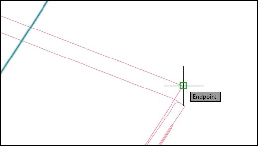
- Specify through point or [Exit, Multiple, Undo]: On the NE side of bridge, use Endpoint OSnap and select the outside bridge apron edge.
- Polyline is created. Select ESC to end command.
Info: In AutoCAD, using the offset command on an alignment results in a polyline.
- Commandline: Type OFFSETEnter
- Specify offset distance or [Through, Erase, Layer]: type TEnter
- Select object to offset or [Exit, Undo]: Select the alignment > Selection Cycling > Alignment
- Specify through point or [Exit, Multiple, Undo]: On the NW side of bridge, use Endpoint OSnap and select the outside bridge apron edge.
- Change layer.
- Ribbon > Home tab > Layers panel > Layer dropdown
- Scroll and select P_BMGRD
- Add transition block to NE quadrant.
- Ribbon > WisDOT Design tab > Manage Panel > select Palettes
- Design Palettes panel > Parametric Blocks dropdown > select Beam Guard Blocks
- Tool Palette > select Beam Guard Detail tab > select MGS Thrie Beam Transition Curve In since this section has a curve.
- Specify insertion location or [Basepoint, Scale, Rotate]: left-click in an open area of the drawing to place.
Tip: Placing the block can cause it to flip, so placing it in an open space in the drawing before snapping into final location can prevent this from happening.
- Edit Attributes dialog box
- Usually there are no attributes to change. Select Cancel.
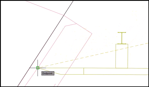
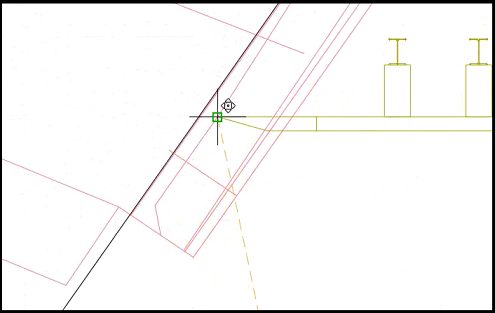
- Select block > select origin (square) point and drag over to the bridge, with Endpoint OSnap active, identify the first endpoint you can snap to on the inside of the wing wall. Click the point.
- Next to the square grip point, select the down arrow and select Show notes.
- Esc to deselect block.
- Measure the radius.
- Ribbon > Analyze tab > Inquiry panel > select Line and Arc Information

- Select object or [Points]: select the curved portion of the offset polyline.
- In Commandline, look for the radius value (2882.774).
Tip: If the information disappears, select F2 to expand commandline and F2 to collapse again.
- Esc to end command.
- Ribbon > Analyze tab > Inquiry panel > select Line and Arc Information
- Enter radius value into block properties.
- Select block > right-click menu > select Properties
- In Properties palette > Custom section, change radTotalShldr value: 2882.774Enter
- Commandline: type REEnter to regenerate screen.
- Posts are on the wrong side, reverse them.
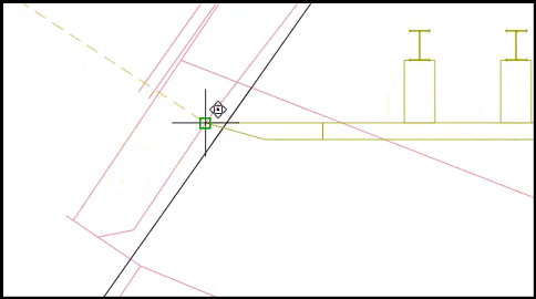
- Select block > select origin point > right-click menu > select Mirror
- Specify second point or [Base point, Copy, Undo, eXit]: Endpoint OSnap to the face of the rail.
- Rotate block.
- Select block > select origin point > right-click menu > select Rotate
- The indicator line does not match up to the face of rail and needs to be corrected.
- Specify rotation angle or [Base point, Copy, Undo, Reference, eXit]: type REnter
- Specify reference angle: select origin point.
- Specify second point: select the face of rail endpoint.
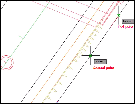
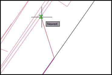
- Specify new angle or [Base point, Copy, Undo, Reference, eXit]:Shift + right-click > Nearest OSnap and select the construction line.
- Esc to deselect block.
Continue adding transition blocks to other quadrants
crdr-ele-bg-eat-c3d24-03.mp4 4:34
- Add transition block to NW quadrant.
- Tool Palette > select Beam Guard Detail tab > select MGS Thrie Beam Transition Curve Out since this section has a curve.
- Specify insertion location or [Basepoint, Scale, Rotate]: left-click in an open area of the drawing to place.
- Edit Attributes dialog box
- Select Cancel.
- Select block > select origin point and drag over to the bridge. With Endpoint OSnap active, identify the first endpoint you can snap to on the inside of the wing wall. Click the point.
- Properties palette > Custom section, change Visibility1 to Show notes.
- Esc to deselect block.
- Measure the radius.
- Ribbon > Analyze tab > Inquiry panel > select Line and Arc Information
- Select object or [Points]: select the curved portion of the offset polyline.
- In Commandline, look for the radius value (2846.789').
Tip: If the information disappears, select F2 to expand commandline and F2 to collapse again.
- Esc to end command.
- Ribbon > Analyze tab > Inquiry panel > select Line and Arc Information
- Enter radius value into block properties.
- In Properties palette > Custom section, change radTotalShldr value: 2846.789Enter
- Commandline: type REEnter to regenerate screen.
- Mirror and/or rotate block as needed, using Nearest Osnap to snap to the construction line.
- Esc to deselect block.
- Add transition block to SE quadrant.
- Tool Palette > select Beam Guard Detail tab > select MGS Thrie Beam Transition since the line is in tangent to the curve.
- Specify insertion location or [Basepoint, Scale, Rotate]: left-click in an open area of the drawing to place.
- Select block > select origin point and drag over to the bridge. With Endpoint OSnap active, identify the first endpoint you can snap to on the inside of the wing wall. Click the point.
- Properties palette > Custom section, change Visibility1 to Show notes.
- Mirror and/or rotate block as needed, using Nearest Osnap to snap to the construction line.
- Esc to deselect block.
- Add transition block to SW quadrant.
- Tool Palette > select Beam Guard Detail tab > select MGS Thrie Beam Transition since the line is in tangent to the curve.
- Specify insertion location or [Basepoint, Scale, Rotate]: left-click in an open area of the drawing to place.
- Select block > select origin point and drag over to the bridge. With Endpoint OSnap active, identify the first endpoint you can snap to on the inside of the wing wall. Click the point.
- Mirror and/or rotate block as needed, using Nearest Osnap to snap to the construction line.
- Esc to deselect block.
Add EAT blocks
crdr-ele-bg-eat-c3d24-04.mp4 8:11
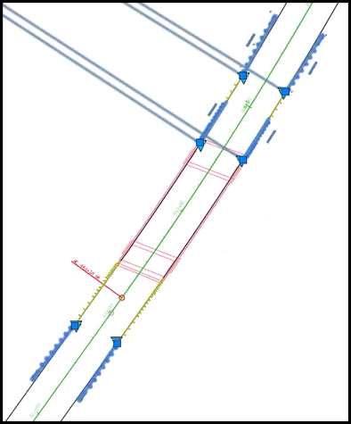
Returning to the NE quadrant, the EATs need to be added 25' from the transition blocks.
- Add a temporary arc segment as a place holder. This will be deleted later.
- Ribbon > Home tab > Draw panel > Arc tool dropdown
 > select Start, Center, End
 - Specify start point of arc or [Center]: Endpoint OSnap to the end of the transition block.
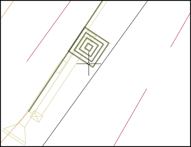
- Specify center point of arc:Shift + right-click > Center OSnap > hover over the construction line and left-click.Because the P_BMGRD layer is active, the arc segment will look like beam guard. Remember, this is a temporary place holder.
- Specify end point of arc (hold Ctrl to switch direction) or [Angle, chord Length]: type LEnter
- Specify length of chord (hold Ctrl to switch direction): type 25Enter
- Esc to deselect (may want to do this a couple times).
- Ribbon > Home tab > Draw panel > Arc tool dropdown
- Add EAT block to NE quadrant.
- Tool Palette > select Beam Guard Detail tab > select MGS EAT Curve In
- Specify insertion location or [Basepoint, Scale, Rotate]: left-click in an open area of the drawing to place.
- Edit Attributes dialog box
- Select Cancel.
- In Properties palette > Custom section, change radTotalShldr value: 2882.774and change Visibility1 to Show notesEnter.
- Select block > select origin point and, with Endpoint OSnap active, left-click the end point of the arc.
- Posts are on the wrong side, reverse them.
- Select block > select origin point > right-click menu > select Mirror
- Specify second point or [Base point, Copy, Undo, eXit]: Endpoint OSnap to the end of construction stub.
- Rotate block.
- Select block > select origin point > right-click menu > select Rotate
- The indicator line does not match up to the end of the construction stub and needs to be corrected.
- Specify rotation angle or [Base point, Copy, Undo, Reference, eXit]: type REnter
- Specify reference angle: select origin point.
- Specify second point: select the endpoint of the construction stub.
- Specify new angle or [Base point, Copy, Undo, Reference, eXit]:Shift + right-click > Nearest OSnap and select the construction line.
- Commandline: type REEnter to regenerate screen.
- Esc to deselect (may want to do this a couple times).
- Select temporary arc segment and Delete.
- In NW quadrant, add a temporary arc segment.
- Ribbon > Home tab > Draw panel > Arc tool dropdown > select Start, Center, End
- Specify start point of arc or [Center]: Endpoint OSnap to the face of rail.
- Specify center point of arc:Shift + right-click > Center OSnap > hover over the construction line and left-click.
- Specify end point of arc (hold Ctrl to switch direction) or [Angle, chord Length]: type LEnter
- Specify length of chord (hold Ctrl to switch direction): type 25Enter
- Esc to deselect (may want to do this a couple times).
- Ribbon > Home tab > Draw panel > Arc tool dropdown
- Add EAT block to NW quadrant.
- Tool Palette > select Beam Guard Detail tab > select MGS EAT Curve Out
- Specify insertion location or [Basepoint, Scale, Rotate]: left-click in an open area of the drawing to place.
- Edit Attributes dialog box
- Select Cancel.
- Select block > select origin point and, with Endpoint OSnap active, left-click the end point of the arc.
- In Properties palette > Custom section, change radTotalShldr value: 2846.789and change Visibility1 to Show notesEnter.
- Commandline: type REEnter to regenerate screen.
- Mirror and/or rotate block as needed, using Nearest Osnap to snap to the construction line.
- Esc to deselect (may want to do this a couple times).
- Select temporary arc segment and Delete.
Going to the south quadrants. Since these run tangent, we are going to use a circle as a temporary place holder.
- In SE quadrant, add a temporary circle.
- Commandline: type CIRCLEEnter
- Specify center point for circle: Endpoint OSnap to the face of rail.
- Specify radius of circle or [Diameter]: type 25Enter
- In SW quadrant, add a temporary circle.
- Commandline: type CIRCLEEnter
- Specify center point for circle: Endpoint OSnap to the face of rail.
- Specify radius of circle or [Diameter]: type 25Enter
- Add EAT block to both south quadrants.
- Tool Palette > select Beam Guard Detail tab > select MGS EAT
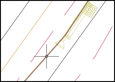
- Specify insertion location or [Basepoint, Scale, Rotate]:Shift + right-click > Apparent Intersect OSnap to the point where the circle crosses the construction line on SE quadrant.
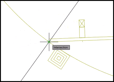
- Tool Palette > select Beam Guard Detail tab > select MGS EAT
- Specify insertion location or [Basepoint, Scale, Rotate]:Shift + right-click > Apparent Intersect OSnap to the point where the circle crosses the construction line on SW quadrant.
- Delete temporary circles.
- Ctrl + select circles and Delete
- Mirror and/or rotate each block as needed, using Nearest Osnap to snap to the construction line.
- Esc to deselect (may want to do this a couple times).
Add guardrail to transition blocks
crdr-ele-bg-eat-c3d24-05.mp4 6:00
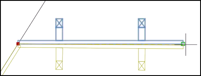
Returning to the north side of the bridge.
- Add guardrail to the end of thrie beam transition, in NE quadrant.
- Tool Palette > select Beam Guard Detail tab > select MGS Guardrail 12.5' - Wood Post
- Specify insertion location or [Basepoint, Scale, Rotate]:Endpoint OSnap to the end of the transition block.
- Posts are on the wrong side, reverse them.
- Select block > select origin point > right-click menu > select Mirror
- Specify second point or [Base point, Copy, Undo, eXit]: Endpoint OSnap to the face of the guardrail.
- Rotate block.
- Select block > select origin point > right-click menu > select Rotate
- The indicator line does match up to the face of guardrail.
- Specify rotation angle or [Base point, Copy, Undo, Reference, eXit]:Shift + right-click > Nearest OSnap and select the construction line.
- Copy the guardrail.
- Select origin point > right-click menu > Copy
- Specify stretch point: Endpint OSnap to the face of rail.
- Placing the guardrail on a curve will have a gap and will need to be rotated.
- Esc to deselect (may want to do this a couple times).
- Select block > select origin point > right-click menu > select Rotate
- The indicator line does not match up to the end of the construction stub and needs to be corrected.
- Specify rotation angle or [Base point, Copy, Undo, Reference, eXit]: type REnter
- Specify reference angle: select origin point.
- Specify second point: select the face of rail.
- Specify new angle or [Base point, Copy, Undo, Reference, eXit]:Shift + right-click > Nearest OSnap and select the construction line.
- Make sure it lines up with the face of rail of the EAT block.
- Add guardrail to the end of thrie beam transitions, in NW quadrant.
- Tool Palette > select Beam Guard Detail tab > select MGS Guardrail 12.5' - Wood Post
- Specify insertion location or [Basepoint, Scale, Rotate]:Endpoint OSnap to the end of the transition block.
- Mirror and/or rotate block as needed, using Nearest Osnap to snap to the construction line.
- Add another guardrail.
- Tool Palette > select Beam Guard Detail tab > select MGS Guardrail 12.5' - Wood Post
- Specify insertion point or [Basepoint, Scale, Rotate]:Endpoint OSnap to the face of rail.
- Placing the guardrail on a curve will have a gap and will need to be rotated.
- Esc to deselect (may want to do this a couple times).
- Select block > select origin point > right-click menu > select Rotate
- The indicator line does not match up to the end of the construction stub and needs to be corrected.
- Specify rotation angle or [Base point, Copy, Undo, Reference, eXit]: type REnter
- Specify reference angle: select origin point.
- Specify second point: select the face of rail.
- Specify new angle or [Base point, Copy, Undo, Reference, eXit]:Shift + right-click > Nearest OSnap and select the construction line.
- Make sure it lines up with the face of rail of the EAT block.
- Repeat the same processes to the south quadrant. Make sure each block is mirrored and rotated to meet the face of rail of corresponding blocks.
- Once finished, Esc to deselect.
- Change block to Hide notes.
- Either select each block individually or use crossing window select to select as a group. Select blocks that have notes showing.
- Properties palette > Custom section, change Visibility1 to Hide notesEnter.
- Delete Construction lines.
- Esc to deselect any blocks.
- Select each polyline and Delete
Quick Access > Save
Open Aliprof.dwg and create new layer
crdr-ele-bg-eat-c3d24-06.mp4 5:09
- Close the BG.dwg file and start a new file.
- Select Open command > Select File dialog box
- Look in: select
 to the dsgn folder and select aliprof folder
Info: In this project we have decided to create the beam guard area alignments in the AliProf.dwg file. In some projects you may choose to place these alignments closer to the beam guard corridor in the Crdr-Beam Guard.dwg file.
- File Name: select AliProf-25.dwg
- Open
- Look in: select
- Select Open command > Select File dialog box
- Close the Properties palette
- Add Xrefs
- Ribbon > WisDOT Design tab > Manage panel > Xref Tools dropdown > select Load Xref on Layer > Open dialog box
- Browse to Civil 3D Projects > trn-bg-eat-c3d24 > dsgn > edgeline
- Select BG.dwg & bridge.dwg
- Open
- Ribbon > WisDOT Design tab > Manage panel > Xref Tools dropdown > select Load Xref on Layer > Open dialog box
- Quick Access > Save
- Change the layer.
- Ribbon > Home tab > Layers panel > select Layer Properties
- In the Layers Properties Manager, create a new layer.
- In Filters column, select Beam Guard.
- In Name column, select P_BMGRD.
- With P_BMGRD highlighted, go back to Filters column and select All.
- Select Create a New Layer button

- Select the Layer 2 and rename it to P_BMGRD_Blk
- Deselect and reselect layer P_BMGRD_Blk
- Select
 to make layer Active
- A green check mark will appear before the name.
- X to close Layers Properties Manager
Create layout blocks, in south quadrant
crdr-ele-bg-eat-c3d24-07.mp4 5:09
- Add block to SE quadrant.
- Ribbon > WisDOT Design tab > Design Palettes panel > Parametric Blocks dropdown > select Beam Guard Blocks
- Tool palette > Beam Guard Layout tab > select BG EAT R Tangent
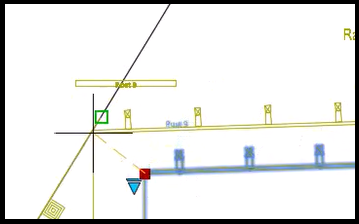
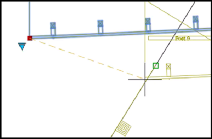
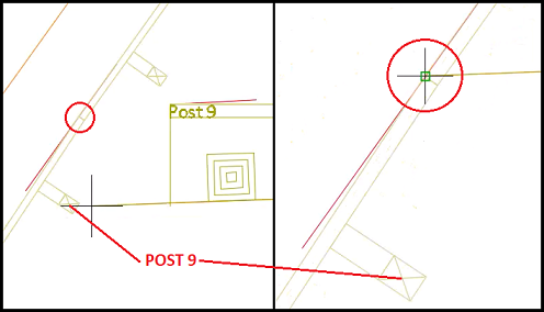
- Specify insertion point or [Basepoint, Scale, Rotate]: Endpoint OSnap to the face of rail at the splice, near Post 9.
- Select the origin point > right-click menu > select Rotate
- Adjust reference indicator line.
- Specify rotation angle or [Base point, Copy, Reference, eXit]: type REnter
- Specify reference angle: select origin point.
- Specify second point: select point where both edge of gravel and edge of hinge dashed lines meet.
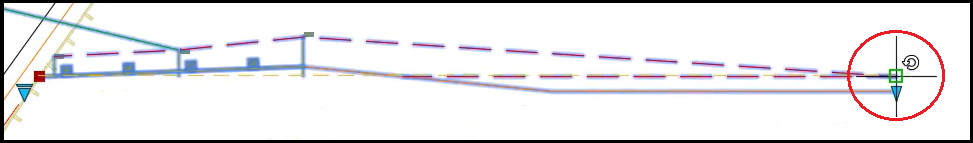
- Specify new angle or [Base point, Copy, Undo, Reference, eXit]:Shift + right-click > Nearest OSnap and select the edge of gravel shoulder alignment.
- Add block to SW quadrant.
- Tool palette > Beam Guard Layout tab > select BG EAT L Tangent
- Specify insertion point or [Basepoint, Scale, Rotate]: Endpoint OSnap to the face of rail at the splice, near Post 9.
- Select the origin point > right-click menu > select Rotate
- Adjust reference indicator line.
- Specify rotation angle or [Base point, Copy, Reference, eXit]: type REnter
- Specify reference angle: select origin point.
- Specify second point: select point where both edge of gravel and edge of hinge dashed lines meet.
- Specify new angle or [Base point, Copy, Undo, Reference, eXit]:Shift + right-click > Nearest OSnap and select the edge of gravel shoulder.
- On this block the edge of paved shoulder is shorter and needs to be adjusted.
- Select the block > right-click menu > select Properties
- In Properties palette > Custom section, change distPavedToTotalShldr to 3.0000Enter.
- Hide the notes.
- Select block > Properties palette > Custom section change Visibility1 to Hide notes
- Repeat for other block.
Quick Access > Save
Create alignment from BG blocks, in south quadrant
crdr-ele-bg-eat-c3d24-08.mp4 5:44
- X to close the Tool palette and Properties palette.
- Create alignments to SE layout block
- Ribbon > WisDOT Design tab > Design panel > Alignment dropdown > select Create Alignments from BG Block
- Select WisDOT Beamguard Block: Select block.
- Select reference Alignment:Select 25 Alignment > selection cycling > select Alignment
- Create alignments to SW layout block
- Ribbon > WisDOT Design tab > Design panel > Alignment dropdown > select Create Alignments from BG Block
- Select WisDOT Beamguard Block: Select block.
- Select reference Alignment:Select 25 Alignment > selection cycling > select Alignment
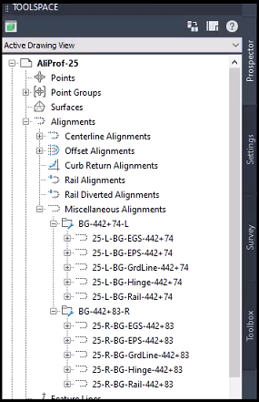
- Confirm alignment were added to the Toolspace.
- Toolspace > Prospector tab > expand Alignments > expand Miscellaneous Alignments and see a folder was created for each block.
- Toolspace > Prospector tab > expand Alignments > expand Miscellaneous Alignments and see a folder was created for each block.
- For this project, the grading lines are not need.
- Toolspace > Prospector tab > expand Alignments > expand Miscellaneous Alignments > expand BG-442+74 L > select 25-L-BG-GrdLine-442+74 > right-click menu > Delete
- Alert: Are you sure you wish to delete '25-L-BG-GrdLine-442+74'? Select Yes.
- Toolspace > Prospector tab > expand Alignments > expand Miscellaneous Alignments > expand BG-442+83 R > select 25-R-BG-GrdLine-442+83 > right-click menu > Delete
- Alert: Are you sure you wish to delete '25-R-BG-GrdLine-442+83'? Select Yes.
- Toolspace > Prospector tab > expand Alignments > expand Miscellaneous Alignments > expand BG-442+74 L > select 25-L-BG-GrdLine-442+74 > right-click menu > Delete
- Quick Access > Save
- Create data shortcuts of all Miscellaneous Alignments
- Toolspace > Prospector tab > select Data Shortcuts > right-click menu > select Create Data Shortcuts > Create Data Shortcuts dialog box
- In Object column, expand Alignments > expand Miscellaneous Alignments
- Select check box Miscellaneous Alignments, this will select all alignments.
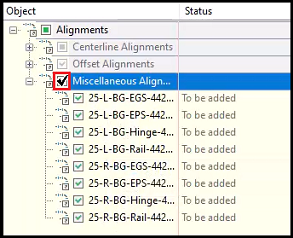
- OK
- Toolspace > Prospector tab > select Data Shortcuts > right-click menu > select Create Data Shortcuts > Create Data Shortcuts dialog box
- Freeze P_BMGRD_Blk layer.
- Ribbon > Home tab > Layers panel > layers dropdown > select P_BMGRD
Info: To freeze a layer, it cannot be the active layer.
- Go back to the Layers dropdown, next to P_BMGRD_Blk and select Thaw button
 and change it to Freeze
  .
.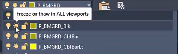
- Go back to the Layers dropdown, type 0 (zero) and select the 0 layer to make it active.
- Ribbon > Home tab > Layers panel > layers dropdown > select P_BMGRD
Extend hinge alignment to bridge, in SE quadrant
crdr-ele-bg-eat-c3d24-09.mp4 6:02
- Starting with the SE Hinge alignment, create a construction line to use as a guide.
- Commandline: type OFFSETEnter
- Specify offset distance or [Through, Erase, Layer]: type TEnter
- Select object to offset or [Exit, Undo]: Select 25 alignment > Selection Cycling > Alignment
- Specify through point or [Exit, Multiple, Undo]: Endpoint OSnap to the to the hinge alignment of the SE layout block.
- Polyline is created. Esc to end command.
- Repeat above process to the SW Hinge alignment side.
- Esc to end command and to deselect any objects.
- Extend hinge alignment of SE quadrant.
- Select Hinge alignment.
- Context ribbon > Modify panel > select Geometry Editor, opens toolbar for this specific alignment.
- Verify the alignment name in the toolbar is the alignment selected, 25-R-BG-Hinge-442+83.
- In the toolbar, select the Line command
 and from the dropdown menu select Fixed Line (Two points).
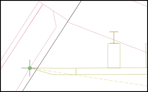
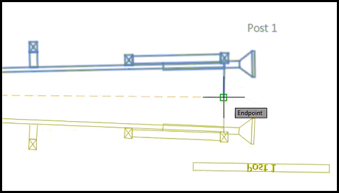
 - Specify start point: Endpoint OSnap to the end of the Hinge alignment.
- Specify next point: Endpoint OSnap to the point where the curve begins.
- In the toolbar, select the Curve command
 and from the dropdown menu select Fixed Curve (Three points).
 - Specify start point: Endpoint OSnap to the end of the line segment.
- Specify second point:Shift + right-click > Nearest OSnap to a point that is midpoint to the bridge.
- Specify end point:Shift + right-click > Nearest OSnap to a point just after the start of the bridge.
- Esc to end command.
- Zoom to the last end point.
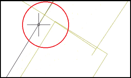
- Create a 45-degree angle to bridge.
- In the toolbar, select the Line command and from the dropdown menu select Fixed Line (Two points).
- Specify start point: Endpoint OSnap to the end of the curve segment.
- Specify next point:Shift + right-click > Nearest OSnap to the bridge at a 45-degree angle.
- In the toolbar, select the Line command
- Enter to end command.
- Verify all points are connected on the hinge alignment.
- Zoom back to see the full alignment.
- Select the Hinge alignment > right-click menu > select Edit Alignment Labels > Alignment Labels dialog box
- Select Import label set
- Select Label Set dialog box
- Label dropdown: select 1IN 40FT-Ticks 100' Major:25' Minor
- OK
- Apply
- Select Label Set dialog box
- Select Import label set
- Review the alignment, checking for continuous label markers.
- If good, select Import label set
- Select Label Set dialog box
- Label dropdown: select _No Labels
- OK
- OK
- Select Label Set dialog box
- Esc to deselect.
- X to close Layout Tools toolbar.
Extend EPS and rail alignments to bridge, in SE quadrant
crdr-ele-bg-eat-c3d24-10.mp4 3:57
- Extend EPS alignment.
- Select EPS alignment. Easiest way to identify it is to find the end of the EAT block.
- Context ribbon > Modify panel > select Geometry Editor, opens toolbar for this specific alignment.
- Verify the alignment name in the toolbar is the alignment selected, 25-R-BG-EPS-442+83.
- In the toolbar, select the Line command and from the dropdown menu select Fixed Line (Two points).
- Specify start point: Endpoint OSnap to the end of the EPS alignment.
- Specify next point: Endpoint OSnap to the point where the curve begins.
- In the toolbar, select the Curve command and from the dropdown menu select Fixed Curve (Three points).
- Specify start point: Endpoint OSnap to the end of the line segment. Zoom in if needed.
- Specify second point:Shift + right-click > Nearest OSnap to a point that is midpoint to the bridge.
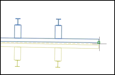
- Specify end point:Endpoint OSnap to the face of the wing wall.
- Esc to end command.
- Select EPS alignment. Easiest way to identify it is to find the end of the EAT block.
- Verify all points are connected on the EPS alignment.
- Zoom back to see the full alignment.
- Select the EPS alignment > right-click menu > select Edit Alignment Labels > Alignment Labels dialog box
- Select Import label set
- Select Label Set dialog box
- Label dropdown: select 1IN 40FT-Ticks 100' Major:25' Minor
- OK
- Select Label Set dialog box
- Apply
- Select Import label set
- Review the alignment, checking for continuous label markers.
- If good, select Import label set
- Select Label Set dialog box
- Label dropdown: select _No Labels
- OK
- OK
- Select Label Set dialog box
- Esc to deselect.
- X to close Layout Tools toolbar.
- Quick Access > Save
- Extend rail alignment.
- Select Rail alignment. This alignment has big blocks along the side.
- Context ribbon > Modify panel > select Geometry Editor, opens toolbar for this specific alignment.
- Verify the alignment name in the toolbar is the alignment selected, 25-R-BG-Rail-442+83.
- In the toolbar, select the Line command and from the dropdown menu select Fixed Line (Two points).
- Specify start point: Endpoint OSnap to the end of the Rail alignment.
- Specify next point: Endpoint OSnap to the point where the curve begins.
- In the toolbar, select the Curve command and from the dropdown menu select Fixed Curve (Three points).
- Specify start point: Endpoint OSnap to the end of the line segment. Zoom in if needed.
- Specify second point:Shift + right-click > Nearest OSnap to a point that is midpoint to the bridge.
- Specify end point:Endpoint OSnap to the face of the wing wall.
- Esc to end command.
- Select Rail alignment. This alignment has big blocks along the side.
- Verify all points are connected on the rail alignment.
- Zoom back to see the full alignment.
- Select the Rail alignment > right-click menu > select Edit Alignment Labels > Alignment Labels dialog box
- Select Import label set
- Select Label Set dialog box
- Label dropdown: select 1IN 40FT-Ticks 100' Major:25' Minor
- OK
- Select Label Set dialog box
- Apply
- Select Import label set
- Review the alignment, checking for continuous label markers.
- If good, select Import label set
- Select Label Set dialog box
- Label dropdown: select _No Labels
- OK
- OK
- Select Label Set dialog box
- Esc to deselect.
- X to close Layout Tools toolbar.
- Select temporary construction line, created as a guide for Hinge alignment, and Delete.
Extend hinge, EPS, and rail alignments, in SW quadrant
crdr-ele-bg-eat-c3d24-11.mp4 3:36
- The temporary construction line was already created.
- Extend hinge alignment of SW quadrant.
- Select Hinge alignment.
- Context ribbon > Modify panel > select Geometry Editor, opens toolbar for this specific alignment.
- Verify the alignment name in the toolbar is the alignment selected, 25-L-BG-Hinge-442+74.
- In the toolbar, select the Line command and from the dropdown menu select Fixed Line (Two points).
- Specify start point: Endpoint OSnap to the end of the Hinge alignment.
- Specify next point: Endpoint OSnap to the point where the curve begins.
- In the toolbar, select the Curve command and from the dropdown menu select Fixed Curve (Three points).
- Specify start point: Endpoint OSnap to the end of the line segment.
- Specify second point:Shift + right-click > Nearest OSnap to a point that is midpoint to the bridge.
- Specify end point:Shift + right-click > Nearest OSnap to a point just after the start of the bridge.
- Esc to end command.
- Zoom to the last end point.
- Create a 45-degree angle to bridge.
- In the toolbar, select the Line command and from the dropdown menu select Fixed Line (Two points).
- Specify start point: Endpoint OSnap to the end of the curve segment.
- Specify next point:Shift + right-click > Nearest OSnap to the bridge at a 45-degree angle.
- In the toolbar, select the Line command
- Enter to end command.
- Verify all points are connected on the hinge alignment.
- Zoom back to see the full alignment.
- Select the Hinge alignment > right-click menu > select Edit Alignment Labels > Alignment Labels dialog box
- Select Import label set
- Select Label Set dialog box
- Label dropdown: select 1IN 40FT-Ticks 100' Major:25' Minor
- OK
- Apply
- Select Label Set dialog box
- Select Import label set
- Review the alignment, checking for continuous label markers.
- If good, select Import label set
- Select Label Set dialog box
- Label dropdown: select _No Labels
- OK
- OK
- Select Label Set dialog box
- Esc to deselect.
- X to close Layout Tools toolbar.
- Select temporary construction line, created as a guide for Hinge alignment, and Delete.
- Extend EPS alignment.
- Select EPS alignment. Easiest way to identify it is to find the end of the EAT block.
- Context ribbon > Modify panel > select Geometry Editor, opens toolbar for this specific alignment.
- Verify the alignment name in the toolbar is the alignment selected, 25-L-BG-EPS-442+74.
- In the toolbar, select the Line command and from the dropdown menu select Fixed Line (Two points).
- Specify start point: Endpoint OSnap to the end of the EPS alignment.
- Specify next point: Endpoint OSnap to the point where the curve begins.
- In the toolbar, select the Curve command and from the dropdown menu select Fixed Curve (Three points).
- Specify start point: Endpoint OSnap to the end of the line segment. Zoom in if needed.
- Specify second point:Shift + right-click > Nearest OSnap to a point that is midpoint to the bridge.
- Specify end point:Shift + right-click Apparent Intersect OSnap to the face of the wing wall.
- Esc to end command.
- Verify all points are connected on the EPS alignment.
- Zoom back to see the full alignment.
- Select the EPS alignment > right-click menu > select Edit Alignment Labels > Alignment Labels dialog box
- Select Import label set
- Select Label Set dialog box
- Label dropdown: select 1IN 40FT-Ticks 100' Major:25' Minor
- OK
- Select Label Set dialog box
- Apply
- Select Import label set
- Review the alignment, checking for continuous label markers.
- If good, select Import label set
- Select Label Set dialog box
- Label dropdown: select _No Labels
- OK
- OK
- Select Label Set dialog box
- Esc to deselect.
- X to close Layout Tools toolbar.
- Extend rail alignment.
- Select Rail alignment. This alignment has big blocks along the side.
- Context ribbon > Modify panel > select Geometry Editor, opens toolbar for this specific alignment.
- Verify the alignment name in the toolbar is the alignment selected, 25-L-BG-Rail-442+74.
- In the toolbar, select the Line command and from the dropdown menu select Fixed Line (Two points).
- Specify start point: Endpoint OSnap to the end of the Rail alignment.
- Specify next point: Endpoint OSnap to the point where the curve begins.
- In the toolbar, select the Curve command and from the dropdown menu select Fixed Curve (Three points).
- Specify start point: Endpoint OSnap to the end of the line segment. Zoom in if needed.
- Specify second point:Shift + right-click > Nearest OSnap to a point that is midpoint to the bridge.
- Specify end point:Endpoint OSnap to the face of the wing wall.
- Esc to end command.
- Verify all points are connected on the rail alignment.
- Select the Rail alignment > right-click menu > select Edit Alignment Labels > Alignment Labels dialog box
- Select Import label set
- Select Label Set dialog box
- Label dropdown: select 1IN 40FT-Ticks 100' Major:25' Minor
- OK
- Apply
- Select Import label set
- Review the alignment, checking for continuous label markers.
- If good, select Import label set
- Select Label Set dialog box
- Label dropdown: select _No Labels
- OK
- OK
- Select Label Set dialog box
- Esc to deselect.
- Select the Rail alignment > right-click menu > select Edit Alignment Labels > Alignment Labels dialog box
- X to close Layout Tools toolbar.
Masking EGS and EPS alignments
crdr-ele-bg-eat-c3d24-12.mp4 2:31
- Edit both EGS and EPS to connect to the layout blocks
- Select original EGS alignment in SE quadrant
- Context ribbon > Modify panel > select Alignment Properties > Alignment Propertied dialog box
- Masking tab, select the Start Masking Region button
 .
. - Specify first station for masking region: Endpoint OSnap to where the hinge alignment, from the block, starts.
- Specify second station for masking region: Left-click on the EGS alignment in the north.
Info: Normally you would attach to the alignment in the north quadrant, but in this session the north is unfinished.
- Alignment Properties dialog box, select OK
- Select the original EPS alignment in SE quadrant
- Context ribbon > Modify panel > select Alignment Properties > Alignment Propertied dialog box
- Masking tab, select the Start Masking Region button .
- Specify first station for masking region: hover over the hinge alignment and Endpoint OSnap to the same station point as the EGS.
- Specify second station for masking region: Left-click on the EGS alignment in the north, near the EGS endpoint.
- Alignment Properties dialog box, select OK
- Repeat the process for original EGS and EPS in SW quadrant.
Quick Access > Save
Adding TBT curb and gutter: create temporary polyline
crdr-ele-bg-eat-c3d24-13.mp4 5:05
Info: This project requires a TBT curb and gutter. Not all projects will require this design.
Requirement: Will need to reference requirement document SDD-08D03-09b Sections E & F.
- Create offset from rail alignment in SE quadrant.
- Commandline: type OFFSETEnter
- Specify offset distance or [Through, Erase, Layer]: type 2.062Enter
- Select object to offset [Exit, Undo]: select Rail alignment, the square boxes are easiest to select from.
- Specify point on side to offset or [Exit, Multiple, Undo]: Left-click to the inside.
- Create offset from rail alignment in SW quadrant.
- Commandline: type OFFSETEnter
- Specify offset distance or [Through, Erase, Layer]: type 2.062Enter
- Select object to offset [Exit, Undo]: select Rail alignment
- Specify point on side to offset or [Exit, Multiple, Undo]: Left-click to the inside.
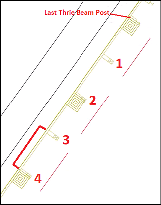
- Go back to the polyline on SE side and create a break at the point where the TBT curb & gutter begins. To identify the beginning point, find the transition point of the thrie beam and guardrail. The start point will be between post 3 and 4, south of the transition.
- Commandline: type BREnter
- Select object: select the polyline just south of post 4.
- Specify second break point or [First point]:Shift + right-click > menu > select Mid Between 2 Points
- First point of mid: select post 4
- Second point of mid: select post 3
- The break is created between posts 3 and 4.
- Esc to end command.
- Select the remaining polyline, south of the break, and Delete.
- Go back to the polyline on SW side and repeat process.
- Commandline: type BREnter
- Select object: select the polyline just south of post 4.
- Specify second break point or [First point]:Shift + right-click > menu > select Mid Between 2 Points
- First point of mid: select post 4
- Second point of mid: select post 3
- Esc to end command.
- Select the remaining polyline, south of the break, and Delete.
Adding TBT curb and gutter: convert polylines to alignments
crdr-ele-bg-eat-c3d24-14.mp4 3:01
- Change SE polyline to alignment
- Ribbon > Home tab > Create Design panel > Alignment dropdown > select Create Alignment from Objects
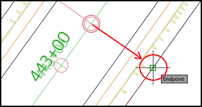
- Select the first line/arc/polyline ot [Xref]: select south end of SE polyline.
- Select lines/arcs or polylines to create alignment:Enter to end command and an arrow pointing north appears on the polyline
Info: Having the arrow pointing north keeps with the flow of the project, but is not necessary.
- Press enter to accept alignment direction or [Reverse]:Enter to accept.
Info: If the arrow on the polyline is pointing the wrong direction, type R to reverse it.
- Create Alignment from Objects dialog box
- Name: type 25-R-TBT-CG-Flag-443+00
- Type: Miscellaneous
- Alignment style: RDWY Curb&Gutter Flange
- Alignment label set: _No Labels
- Conversion options: Uncheck Add curves between tangents and Check Erase existing entities.
- OK
- Change SW polyline to alignment
- Ribbon > Home tab > Create Design panel > Alignment dropdown > select Create Alignment from Objects
- Select the first line/arc/polyline ot [Xref]: select south end of SE polyline.
- Select lines/arcs or polylines to create alignment:Enter to end command and an arrow pointing north appears on the polyline
- Press enter to accept alignment direction or [Reverse]:Enter to accept.
- Create Alignment from Objects dialog box
- Name: type 25-L-TBT-CG-Flag-443+00
- Type: Miscellaneous
- Alignment style: RDWY Curb&Gutter Flange
- Alignment label set: _No Labels
- Conversion options: Uncheck Add curves between tangents and Check Erase existing entities.
- OK
Adding TBT curb and gutter: offset alignments
crdr-ele-bg-eat-c3d24-15.mp4 3:24
- Offset SE TBT Flag alignment.
- Ribbon > WisDOT Design tab > Design panel > Alignment dropdown > select Create Curb Offsets
- Offset to face (Enter to skip): type 2.33Enter
Tip: Measurement needs to be in feet.
- Offset to back (Enter to skip): type 3Enter
- Select Alignment [Offset]: select SE TBT Flag alignment
- Alignment Range [Entire, Pick] <Entire>:Enter to accept.
- Pick side: Left-click to the outside.
- Esc to deselect.
- Offset SW TBT Flag alignment.
- Ribbon > WisDOT Design tab > Design panel > Alignment dropdown > select Create Curb Offsets
- Offset to face (Enter to skip): type 2.33Enter
- Offset to back (Enter to skip): type 3Enter
- Select Alignment [Offset]: select SW TBT Flag alignment
- Alignment Range [Entire, Pick] <Entire>:Enter to accept.
- Pick side: Left-click to the outside.
- Right-click menu > Enter to end command.
Quick Access > Save
- Create data shortcuts od TBT alignments.
- Toolspace > Prospector tab > right-click Data Shortcuts > select Create Data Shortcuts
- Create Data Shortcuts dialog box
- Expand Offset Alignments, check boxes for 25-NB-L-TBT-CG-443+00-Back. 25-NB-L-TBT-CG-443+00-Front, 25-NB-R-TBT-CG-443+00-Back, and 25-NB-R-TBT-CG-443+00-Front.
- Expand Micellaneous Alignments, check boxes for 25-NB-L-TBT-CG-Flag-443+00 and 25-NB-R-TBT-CG-Flag-443+00.
- OK
Quick Access > Save
Create pavement edgeline file
crdr-ele-bg-eat-c3d24-16.mp4 4:48
- Starting with a new file and save it.
- Quick Access > select New
- Menu Browser > select Save As > Save Drawing As dialog box
- Save in: C: > Civil 3D Projects > trn-bg-eat-c3d24 > dsgn > edgeline
- File name: type pavt.dwg
- Save
- Check the working and data shortcut project folder are correct.
- Toolspace > Prospector tab > hover over Data Shortcuts
- Path should be C:\Civil 3D Projects\trn-bg-eat-c3d24
- Add data references.
- Data Shortcuts > expand Alignments > expand Offset Alignments
- Shift + select all offset alignments listed; 25-L-EGS-1, 25-L-EPS-1, 25-L-ETW-1, 25-NB-L-TBT-CG-Back,25-NB-L-TBT-CG-Front, 25-NB-R-TBT-CG-Back,25-NB-R-TBT-CG-Front, 25-R-EGS-1, 25-R-EPS-1, and 25-R-ETW-1,
- Right-click on one of them > menu > select Create Reference
- Commandline: type ZEEnter (zoom extents)
- Commandline: type REEnter to regenerate file.
- Toolspace > Prospector tab > Data Shortcuts > expand Alignments > expand Miscellaneous Alignments
- Shift + select all miscellaneous alignments listed; BG-442+74-L (folder), BG-442+83-R (folder), 25-NB-L-TBT-CG-Flag, and 25-NB-R-TBT-CG-Flag.
- Right-click on one of them > menu > select Create Reference
- Data Shortcuts > expand Alignments > expand Offset Alignments
- Assign alignment styles.
- Ribbon > WisDOT Design tab > Design panel > Alignment dropdown > select Assign Alignment Styles
Info: This is driven by an Excel spreadsheet to automate style and label assignents based on alignment names.
- Select Style data file [Apply default, View default, browse Current, browse Last]: type AEnter
- Assign Alignment styles [All, Select]: type AEnter
- Ribbon > WisDOT Design tab > Design panel > Alignment dropdown > select Assign Alignment Styles
- Select the Rail alignments and Delete.
- If there are green grading alignments, delete them too.
- Close off the ends of the TBT Curb and Gutters.
- Change the layer.
- Ribbon > Home tab > Layers panel > Layers dropdown > select P_RDWY_C_and_G
- Draw a polyline across the ends.
- Ribbon > Home tab > Draw panel > select Polyline tool

- Starting with the SW C&G, south end, Endpoint OSnap to the back of curb, face of curb, and flag of curb.
- Ribbon > Home tab > Draw panel > select Polyline tool
- Repeat Step B for each end; SW C&G north end, SE C&G north end, and SE C&G south end.
- Change the layer.
Quick Access > Save
Build a corridor
crdr-ele-bg-eat-c3d24-17.mp4 6:20
- Starting with a new file and save it.
- Quick Access > select New
- Menu Browser > select Save As > Save Drawing As dialog box
- Save in: C: > Civil 3D Projects > trn-bg-eat-c3d24 > dsgn > crdr
- File name: type Crdr-25-BG.dwg
- Save
- Check the working and data shortcut project folder are correct.
- Toolspace > Prospector tab > hover over Data Shortcuts
- Path should be C:\Civil 3D Projects\trn-bg-eat-c3d24
- Add Xrefs.
- Ribbon > WisDOT Design tab > Manage panel > Xref Tools dropdown > select Load Xref of Layer > Open dialog box
- Browse to C: > Civil 3D Projects > trn-bg-eat-c3d24 > dsgn > select edgeline folder
- Select both BG.dwg and bridge.dwg
- Open
- Commandline: type ZEEnter (zoom extents)
- Ribbon > WisDOT Design tab > Manage panel > Xref Tools dropdown > select Load Xref of Layer > Open dialog box
- Create surface reference.
- Toolspace > Prospector tab > expand Data Shortcuts > expand Surfaces > right-click Exist > select Create Reference > Create Surface Reference dialog box
- Surface Layer: select Select Layer button

- Object Layer dialog box
- Base Layer name: select Select Layer button

- Layer Selection dialog box
- Scroll and select E_SURF
- OK
- Layer Selection dialog box
- Modifer: Suffix
- Modifer value: _* (underscore+asterisk)
- Preview: autofills and reads E_SURF_Exist
- OK
- Base Layer name: select Select Layer button
- Object Layer dialog box
- Properties, Style: left-click in Value field and select ellipsis button

- Select Surface Style dialog box
- Dropdown > select EX Border
- OK
- Select Surface Style dialog box
- OK
- Surface Layer: select Select Layer button
- Toolspace > Prospector tab > expand Data Shortcuts > expand Surfaces > right-click Exist > select Create Reference > Create Surface Reference dialog box
- Add data references.
- Toolspace > Prospector tab > expand Data Shortcuts > expand Alignments > expand Centerline Alignments > right-click 25 > select Create Reference > Create Alignment Reference dialog box
- No changes
- OK
- Toolspace > Prospector tab > expand Data Shortcuts > expand Alignments > expand Centerline Alignments > expand 25 > expand Profiles > right-click 25-Prop > select Create Reference > Create Alignment Reference dialog box
- Profile label set: change to WisDOT Standard
- OK
- Toolspace > Prospector tab > expand Data Shortcuts > expand Alignments > expand Offset Alignments
- Shift + select all offset alignments listed; 25-L-EGS-1, 25-L-EPS-1, 25-L-ETW-1, 25-NB-L-TBT-CG-Back,25-NB-L-TBT-CG-Front, 25-NB-R-TBT-CG-Back,25-NB-R-TBT-CG-Front, 25-R-EGS-1, 25-R-EPS-1, and 25-R-ETW-1.
- Right-click on one of them > menu > select Create Reference
- Toolspace > Prospector tab > Data Shortcuts > expand Alignments > expand Miscellaneous Alignments
- Shift + select all miscellaneous alignments listed; BG-442+74-L (folder), BG-442+83-R (folder), 25-NB-L-TBT-CG-Flag, and 25-NB-R-TBT-CG-Flag.
- Right-click on one of them > menu > select Create Reference
- Toolspace > Prospector tab > expand Data Shortcuts > expand Alignments > expand Centerline Alignments > right-click 25 > select Create Reference > Create Alignment Reference dialog box
- Assign alignment styles.
- Ribbon > WisDOT Design tab > Design panel > Alignment dropdown > select Assign Alignment Styles
- Select Style data file [Apply default, View default, browse Current, browse Last]: type AEnter
- Assign Alignment styles [All, Select]: type AEnter
Quick Access > Save
- Create control profiles to help with future profile targeting.
- Ribbon > WisDOT Design tab > Design panel > Profile dropdown > select Control Profile Editor > Control Profile Editor dialog box
- Alignment: 25
- Multiple: check box Default
- Create
- Review list and select Continue.
- Close
- Ribbon > WisDOT Design tab > Design panel > Profile dropdown > select Control Profile Editor > Control Profile Editor dialog box
Quick Access > Save
Add assemblies data
crdr-ele-bg-eat-c3d24-18.mp4 3:05
- Add assemblies data.
- Ribbon > WisDOT Design tab > Design Palettes panel > select WisDOT Subassemblies
Tip: If palette doesn't open, go to Manage panel and select Palettes.
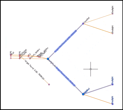
- Tool Palette > Beam Guard Assemblies tab > select Beam Guard Rehab
- Specify location for Assembly: select an open area of the drawing.
- Esc to end command.
- Zoom in to the assembly.
- Select the assembly > right-click menu > select Assembly Properties
- Assembly Properties - Beam Guard - Rehab dialog box
- Name: type 25-BG-Rehab-L-NoCG
- OK
- Assembly Properties - Beam Guard - Rehab dialog box
- Esc to deselect.
- Tool Palette > Beam Guard Assemblies tab > select Beam Guard - Rehab - Thrie Beam Transition
- Specify location for Assembly: select an open area of the drawing, placing it above the other assembly.
- Esc to end command.
- Select the assembly > right-click menu > select Assembly Properties
- Assembly Properties - Beam Guard - Rehab dialog box
- Name: type 25-BG-Rehab-L-CG
- OK
- Assembly Properties - Beam Guard - Rehab dialog box
- Esc to deselect.
- Ribbon > WisDOT Design tab > Design Palettes panel > select WisDOT Subassemblies
- X to close Tool Palette.
Edit assembly parameters for 25-BG-Rehab-L-NoCG
crdr-ele-bg-eat-c3d24-19.mp4 4:45
- Edit assembly perimeters.
- Select assembly 25-BG-Rehab-L-NoCG
- Context ribbon > Modify Assembly panel > select Assembly Properties > Assembly Properties dialog box
- Codes tab
- Code set style dropdown: select General - Point Codes
- Apply
- Construction tab
- Baseline > Right > select PavedShld-R
- Change Input value of Base1 thickness to 9". Enter
- Baseline > Right > select PavedShld-R
- Apply
- Baseline > Right > select UnpavedShld-R
- Verify Input value of Paved shoulder superelevation is Use outside shoulder SE.
- Verify Input value of Unpaved shoulder superelevation is User defined.
- Verify Input value of Unpaved shoulder slope is -10.00%.
- Change Input value of Include surface widening points to YesOK.
- Baseline > Left > PavedShld-L
- Change Input value of Base1 thickness to 9". Enter
- Baseline > Right > select UnpavedShld-R
- Apply
- Baseline > Left > UnpavedShld-L
- Verify Input value of Paved shoulder superelevation is Use outside shoulder SE.
- Verify Input value of Unpaved shoulder superelevation is User defined.
- Verify Input value of Unpaved shoulder slope is -10.00%.
- Change Input value of Include surface widening points to YesOK.
- Baseline > Left > UnpavedShld-L
- OK
- Codes tab
- Esc to deselect.
Edit assembly parameters for 25-BG-Rehab-L-CG
crdr-ele-bg-eat-c3d24-20.mp4 3:55
- Edit assembly perimeters.
- Select assembly 25-BG-Rehab-L-CG
- Context ribbon > Modify Assembly panel > select Assembly Properties > Assembly Properties dialog box
- Codes tab
- Code set style dropdown: select General - Point Codes
- Apply
- Construction tab
- Baseline > Right > select PavedShldCG-R
- Change Input value of Base1 thickness to 9". Enter
- Baseline > Right > select PavedShldCG-R
- Apply
- Continue with Baseline > Right > select PavedShldCG-R
- If there is an Input value for [P2 to P1] Top, select and Delete.
- Baseline > Right > select CGBasic
- Verify Input value of Curb and gutter size is Wi 36".
- Verify Input value of Wi 36" curb type is TBT.
- Verify Input value of Gutter slope method is Standard.
- Baseline > Right > select UnpavedShld-R
- Verify Input value of Paved shoulder superelevation is Use outside shoulder SE.
- Verify Input value of Unpaved shoulder superelevation is User defined.
- Verify Input value of Unpaved shoulder slope is -10.00%.
- Change Input value of Include surface widening points to YesOK.
- Baseline > Left > select PavedShldCG-L
- Change Input value of Base 1 thickness to 9". Enter
- Continue with Baseline > Right > select PavedShldCG-R
- Apply
- Continue with Baseline > Left > select PavedShldCG-L
- If there is an Input value for [P2 to P1] Top, select and Delete.
- Baseline > Left > select CGBasic
- Verify Input value of Curb and gutter size is Wi 36".
- Verify Input value of Wi 36" curb type is TBT.
- Verify Input value of Gutter slope method is Standard.
- Baseline > Left > select UnpavedShld-L
- Verify Input value of Paved shoulder superelevation is Use outside shoulder SE.
- Verify Input value of Unpaved shoulder superelevation is User defined.
- Verify Input value of Unpaved shoulder slope is -10.00%.
- Change Input value of Include surface widening points to YesOK.
- Continue with Baseline > Left > select PavedShldCG-L
- OK
- Codes tab
- Esc to deselect.
Edit assemblies: removing grading alignment's conditional data
crdr-ele-bg-eat-c3d24-21.mp4 2:14
For this project, the green grading alignments were deleted. The conditional data for them needs to be deleted as well.
Warning: If you are using the grading line in your project, SKIP THIS STEP.
- Zoom to the assembly 25-BG-Rehab-L-NoCG.
- On the right side, using crossing window select, select the conditional Target Found subassembly and Daylight subassembly. Select the conditional Target Not Found subassembly, but leave the Daylight subassembly.
- Delete
- Commandline: type REEnter, to regenerate the drawing.
- On the left side, using crossing window select, select the conditional Target Found subassembly and Daylight subassembly. Select the conditional Target Not Found subassembly, but leave the Daylight subassembly.
- Delete
- Commandline: type REEnter
- On the right side, using crossing window select, select the conditional Target Found subassembly and Daylight subassembly. Select the conditional Target Not Found subassembly, but leave the Daylight subassembly.
- Zoom to the assembly 25-BG-Rehab-L-CG. To speed this up, select both sides.
- On the right side, using crossing window select, select the conditional Target Found subassembly and Daylight subassembly. Select the conditional Target Not Found subassembly, but leave the Daylight subassembly.
- On the left side, using crossing window select, select the conditional Target Found subassembly and Daylight subassembly. Select the conditional Target Not Found subassembly, but leave the Daylight subassembly.
- Delete
- Commandline: type REEnter
-
With those edits done, use the MOVE command on the assembly 25-BG-Rehab-L-NoCG to bring it closer to the assembly 25-BG-Rehab-L-CG.
Copy and edit assemblies
crdr-ele-bg-eat-c3d24-22.mp4 4:27
- Copy both assemblies.
- Left click on the green centerline of each assembly.
- Commandline: type COEnter, to copy.
- Specify base point or [Displacement, mOde]: left-click on the left, outside the assemblies.
- Specify second point or [Array]: right-click on the left, outside the assemblies.Look for the floating green lines. They are for the copied assemblies. Make sure to drag them out enough to not overlap the current assemblies.
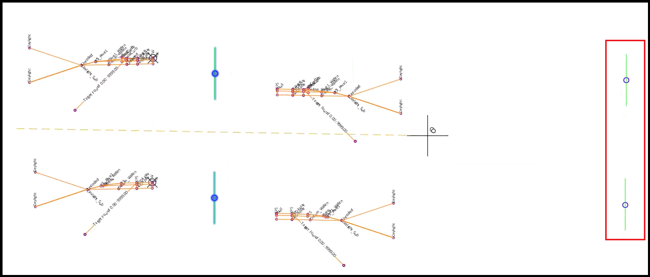
- Esc to deselect.
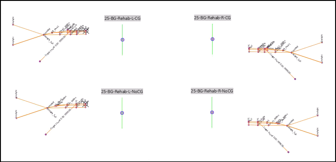
- Rename the new assemblies.
- Select the top assembly > right-click menu > Assembly Properties
- Assembly Properties dialog box
- Name: change to 25-BG-Rehab-R-CG
- OK
- Assembly Properties dialog box
- Select the bottom assembly > right-click menu > Assembly Properties
- Assembly Properties dialog box
- Name: change to 25-BG-Rehab-R-NoCG
- OK
- Assembly Properties dialog box
- Select the top assembly > right-click menu > Assembly Properties
- Edit the assemblies. Remove the right side assemblies from the left and remove the left side assemblies from the right.
- Using cross window select, select all of those assemblies.
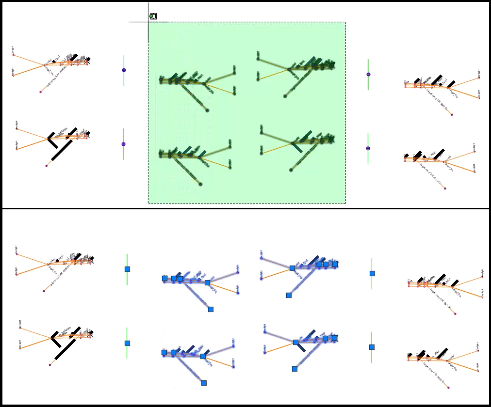
Info: Make sure there is a visible grip point highlighted at the green centerline of each assembly. There are invisible lines connecting those assemblies at these points and needs to be deleted too.
- Delete
- Using cross window select, select all of those assemblies.
- Label assemblies.
- Ribbon > WisDOT Design tab > Design panel > Assemblies dropdown > select Label Assembly
- Enter text size <1.000>:Enter to accept default.
- Assembly selection [All, Individual]: type AEnter
Quick Access > Save
Creating corridor
crdr-ele-bg-eat-c3d24-23.mp4 3:28
- Create corridor.
- Ribbon > Home tab > Create Design panel > Corridor dropdown > select Corridor > Create Corridor dialog box
- Name: type 25-BG
- Corridor style: RDWY Proposed
- Code set style: General
- Alignment and profiles section
- First Alignment field: select > dropdown > select 25
Info: This list will only include alignments with profiles.
- First Profile field: 25-Prop
- First Assembly field: select > dropdown > select 25-BG-Rehab-R-NoCG
- Second Alignment field: select > dropdown > select 25
- Second Profile field: 25-Prop
- Second Assembly field: select > dropdown > select 25-BG-Rehab-L-NoCG
- First Alignment field: select > dropdown > select 25
- Target Surface: dropdown > select Exist
- OK
- Both baselines are built.
- Ribbon > Home tab > Create Design panel > Corridor dropdown > select Corridor > Create Corridor dialog box
Edit baseline and region parameters, right side
crdr-ele-bg-eat-c3d24-24.mp4 5:12
- Baseline and Region Parameters dialog box
- BL-25-(1)
- Edit RG-25-BG-Rehab-R-NoCG
- Start Station field: select Select from Screen button

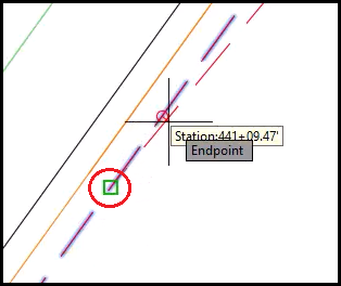
- Specify station along baseline: Endpoint OSnap to the Hinge alignment on the south end, approx. station 441+10.39'.
- End Station field: select Select from Screen button
- Specify station along baseline: Endpoint OSnap to the start of the TBT on the south end, approx. station 442+88.80'.
- Frequency field: select ellipsis
Frequency to Apply Assemblies dialog box
Warning: Setting the frequency this high is very specific to a project scope where the only corridor sample lines will be at special stationing (in this case, at posts 1, 5, & 9 and the begin and end of earthwork
-
- Horizontal Baseline, Along tangents: type 1000000
- Horizontal Baseline, Curve increment: type 1000000
- Horizontal Baseline, Along spirals: type 1000000
- Vertical Baseline, Along vertical curves: type 1000000
- Every Yes/No option: make them Yes
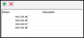
- Select Specify Additional Stations button

- Specify station along baseline: Endpoint OSnap to where the bend begins for the EPS,
- Commandline: Station 441+79.46' was added.
- Specify station along baseline: Midpoint OSnap to the first post, either to the back of the post of the center cross-section.
- Commandline: Station 442+29.49' was added.
- Specify station along baseline: Midpoint OSnap to the fifth post, either to the back of the post of the center cross-section.
- Commandline: Station 442+54.51' was added.
- Specify station along baseline: Midpoint OSnap to the ninth post, either to the back of the post of the center cross-section.
- Commandline: Station 442+79.49' was added.
- Enter to end section.
- Specify station along baseline: Endpoint OSnap to where the bend begins for the EPS,
- See all of the stations listed.
- OK
- Start Station field: select Select from Screen button
- Right-click on RG-25-BG-Rehab-R-NoCG > menu > select Insert Region - After
- Create Corridor Region dialog box
- Assembly: dropdown > select 25-BG-Rehab-R-CG
- OK
- Create Corridor Region dialog box
- Edit RG-25-BG-Rehab-R-CG
- Start station field: 442+88.80'
- End Station field: select Select from Screen button
- Specify station along baseline: Endpoint OSnap to the end of the TBT, approx. station 443+44.27'.
- Frequency field: select ellipsis
- Frequency to Apply Assemblies dialog box
- Horizontal Baseline, Along tangents: type 1000000
- Horizontal Baseline, Curve increment: type 1000000
- Horizontal Baseline, Along spirals: type 1000000
- Vertical Baseline, Along vertical curves: type 1000000
- Every Yes/No option: make them Yes
- Select Specify Additional Stations button
- Specify station along baseline: Midpoint OSnap to the first Thrie Beam Transition post, select the back of the post.
- Commandline: Station 443+10.68' was added.
- Specify station along baseline: Midpoint OSnap to the last Thrie Beam Transition post, select the back of the post.
- Commandline: Station 443+43.29' was added.
- Specify station along baseline: type 44288.81Enter
- Commandline: Station 442+88.81' was added.
- Enter to end section.
- Specify station along baseline: Midpoint OSnap to the first Thrie Beam Transition post, select the back of the post.
- See all of the stations listed.
- OK
- Frequency to Apply Assemblies dialog box
- Edit RG-25-BG-Rehab-R-NoCG
- BL-25-(1)
Edit baseline and region parameters - left side
crdr-ele-bg-eat-c3d24-25.mp4 3:20
- Baseline and Region Parameters dialog box (continued)
- BL-25-(2)
- Edit RG-25-BG-Rehab-L-NoCG
- Start Station field: select Select from Screen button
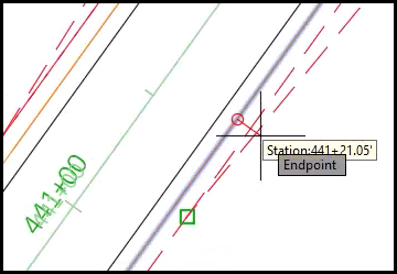
- Specify station along baseline: Endpoint OSnap to the Hinge alignment's endpoint, at the south end, approx. station 441+01.92'.
- End Station field: select Select from Screen button
- Specify station along baseline: Endpoint OSnap to the start of the TBT on the south end, approx. station 442+80.33'.
- Frequency field: select ellipsis
- Frequency to Apply Assemblies dialog box
- Horizontal Baseline, Along tangents: type 1000000
- Horizontal Baseline, Curve increment: type 1000000
- Horizontal Baseline, Along spirals: type 1000000
- Vertical Baseline, Along vertical curves: type 1000000
- Every Yes/No option: make them Yes
- Select Specify Additional Stations button
- Specify station along baseline: Endpoint OSnap to where the bend begins for the EPS,
- Commandline: Station 441+70.99' was added.
- Specify station along baseline: Midpoint OSnap to the first post, either to the back of the post of the center cross-section.
- Commandline: Station 442+21.03' was added.
- Specify station along baseline: Midpoint OSnap to the fifth post, either to the back of the post of the center cross-section.
- Commandline: Station 442+46.05' was added.
- Specify station along baseline: Midpoint OSnap to the ninth post, either to the back of the post of the center cross-section.
- Commandline: Station 442+71.03' was added.
- Enter to end section.
- Specify station along baseline: Endpoint OSnap to where the bend begins for the EPS,
- See all of the stations listed.
- OK
- Frequency to Apply Assemblies dialog box
- Start Station field: select Select from Screen button
- Add another region.
- Right-click on RG-25-BG-Rehab-L-NoCG > menu > select Insert Region - After
- Create Corridor Region dialog box
- Assembly: dropdown > select 25-BG-Rehab-L-CG
- OK
- Edit RG-25-BG-Rehab-L-CG
- Start station field: 442+80.33'
- End Station field: select Select from Screen button
- Specify station along baseline: Endpoint OSnap to the end of the TBT, approx. station 443+36.12'.
- Frequency field: select ellipsis
- Frequency to Apply Assemblies dialog box
- Horizontal Baseline, Along tangents: type 1000000
- Horizontal Baseline, Curve increment: type 1000000
- Horizontal Baseline, Along spirals: type 1000000
- Vertical Baseline, Along vertical curves: type 1000000
- Every Yes/No option: make them Yes
- Select Specify Additional Stations button
- Specify station along baseline: Midpoint OSnap to the first Thrie Beam Transition post, select the back of the post.
- Commandline: Station 443+02.20' was added.
- Specify station along baseline: Midpoint OSnap to the last Thrie Beam Transition post, select the back of the post.
- Commandline: Station 443+35.15' was added.
- Specify station along baseline: type 4428034Enter
- Commandline: Station 442+80.34' was added.
- Enter to end section.
- Specify station along baseline: Midpoint OSnap to the first Thrie Beam Transition post, select the back of the post.
- See all of the stations listed.
- OK
- Frequency to Apply Assemblies dialog box
- Edit RG-25-BG-Rehab-L-NoCG
- BL-25-(2)
Rebuild corridor and assign targets
crdr-ele-bg-eat-c3d24-26.mp4 4:28
- Rebuild the corridor (continued)
- Baseline and Region Parameters dialog box
- OK
- Alert: The corridor definition has been modified and needs to be rebuilt. What do you want to do? Select Rebuild the corridor.
- Baseline and Region Parameters dialog box
- Events panorama opens with a series of errors. These errors should be corrected with the next steps.
- Select Action > Clear All Events
- Green checkmark to close panorama.
- Assign targets.
- Zoom to the corridor.
- Ribbon > WisDOT Design tab > Design panel > Corridor dropdown > select Assign Corridor Targets > Assign Corridor Targets dialog box
- Corridor: 25-BG
- Baseline: dropdown > select first 25 - 25-PropThere are 2 listed here with the same name, be sure to select the first one listed.
- Region (Start Station - End Station): select 441+10.39 - 442+88.80
- Targets section
- Template dropdown: select Crdr TrgtAssgn-BeamGuard.csv
- Select Open Template
- Opens Excel file.
- File > Save As > Browse
- Save As dialog box
- Before browsing, select on file name Crdr TrgtAssgn-BeamGuard.csv to populate the File name field.
- Select Windows (C:) > Civil 3D Projects > trn-bg-eat-c3d24 > dsgn > crdr
- Save
- Save As dialog box
- X to close Excel file.
- File > Save As > Browse
- Opens Excel file.
- Next to Assign, select Open Folder button

- Set Corridor Targets Data File dialog box
- Verify it is opening from Civil 3D Projects > trn-bg-eat-c3d24 > dsgn > crdr folder
- Select Crdr TrgtAssgn-BeamGuard.csv
- Open
- Set Corridor Targets Data File dialog box
- OK
- Look for Process Complete.
- Region (Start Station - End Station): select 442+88.80 - 443+44.27
- OK
- Look for Process Complete.
- Baseline: dropdown > select second 25 - 25-Prop
- Region (Start Station - End Station): select 441+10.39 - 442+88.80
- OK
- Look for Process Complete.
- Region (Start Station - End Station): select 442+88.80 - 443+44.27
- OK
- Look for Process Complete.
- Close
- Rebuild corridor.
- Toolspace > Prospector tab > expand Corridors > right-click 25-BG > select Rebuild
Add TBT targeting
crdr-ele-bg-eat-c3d24-27.mp4 2:33
Info: Thrie Beam Transition targeting has not been added to the WisDOT Automatic Targeting tool.
- Add TBT targeting.
- Select corridor.
- Context ribbon > Modify Corridor panel > select Corridor Properties > Corridor Properties dialog box
- Parameters tab
- Select RG - 25-BG-Rehab-R-CG
- Target field: select ellipsis
- Target Mapping dialog box
- expand open PavedShldCG-R
- select Lane width
- Select alignment and pipe to target: scroll to 25-NB-R-TBT-CG-Flag-443+00 (Right) and check the box.
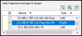
- OK
- Target Mapping dialog box
- Select RG - 25-BG-Rehab-L-CG
- Target field: select ellipsis
- Target Mapping dialog box
- expand open PavedShldCG-L
- select Lane width
- Select alignment and pipe to target: scroll to 25-NB-L-TBT-CG-Flag-443+00 (Left) and check the box.
- OK
- Target Mapping dialog box
- OK
- Alert: The corridor definition has been modified and needs to be rebuilt. What do you want to do? Select Rebuild the corridor.
- Parameters tab
Adjusting slopes behind guardrail, part 1
crdr-ele-bg-eat-c3d24-28.mp4 4:04
- Ribbon > WisDOT tab > Design panel > Profile dropdown > select Control Profile Editor > Control Profile Editor dialog box
- Edit tab
- Alignment: 25
- Control Profile: dropdown > select ZCP-25-R-ShldrFslp
- Edit section
- Station: select Select from Screen button
- Select Station: Midpoint OSnap to the back of the fifth post (SE)
- Station value: type -0.25
- Add
- Station: select Select from Screen button
- Select Station: Midpoint OSnap to the back of the ninth post (SE)
- Station value: type -0.4
- Add
- Station: select Select from Screen button
- Select Station: Midpoint OSnap to the back of the ninth post (NE).
- Station value: type -0.4
- Add
- Station: select Select from Screen button
- Select Station: Midpoint OSnap to the back of the fifth post (NE)
- Station value: type -0.25
- Add
- Station: select Select from Screen button
- Edit tab
Adjusting slopes behind guardrail, part 2
crdr-ele-bg-eat-c3d24-29.mp4 3:31
(Continued from video 28)
- Ribbon > WisDOT tab > Design panel > Profile dropdown > select Control Profile Editor > Control Profile Editor dialog box
- Edit tab
- Alignment: 25
- Control Profile: dropdown > select ZCP-25-R-RcvrFSlp
- Edit section
- Station: select Select from Screen button
- Select Station: Midpoint OSnap to the back of the fifth post (NE)
- Station value: type 0.25
- Add
- Station: select Select from Screen button
- Select Station: Midpoint OSnap to the back of the ninth post (NE).
- Station value: type 0.4
- Add
- Station: select Select from Screen button
- Select Station: Midpoint OSnap to the back of the ninth post (SE)
- Station value: type 0.4
- Add
- Station: select Select from Screen button
- Select Station: Midpoint OSnap to the back of the fifth post (SE)
- Station value: type 0.25
- Add
- Station: select Select from Screen button
- Control Profile: dropdown > select ZCP-25-L-ShldrFslp
- Edit section
- Station: select Select from Screen button
- Select Station: Midpoint OSnap to the back of the fifth post (SW)
- Station value: type -0.25
- Add
- Station: select Select from Screen button
- Select Station: Midpoint OSnap to the back of the ninth post (SW)
- Station value: type -0.4
- Add
- Station: select Select from Screen button
- Select Station: Midpoint OSnap to the back of the ninth post (NW).
- Station value: type -0.4
- Add
- Station: select Select from Screen button
- Select Station: Midpoint OSnap to the back of the fifth post (NW)
- Station value: type -0.25
- Add
- Station: select Select from Screen button
- Control Profile: dropdown > select ZCP-25-L-RcvrFSlp
- Edit section
- Station: select Select from Screen button
- Select Station: Midpoint OSnap to the back of the fifth post (NW)
- Station value: type 0.25
- Add
- Station: select Select from Screen button
- Select Station: Midpoint OSnap to the back of the ninth post (NW).
- Station value: type 0.4
- Add
- Station: select Select from Screen button
- Select Station: Midpoint OSnap to the back of the ninth post (SW)
- Station value: type 0.4
- Add
- Station: select Select from Screen button
- Select Station: Midpoint OSnap to the back of the fifth post (SW)
- Station value: type 0.25
- Add
- Station: select Select from Screen button
- Edit tab
Edit TBT curb head height
crdr-ele-bg-eat-c3d24-30.mp4 6:33
Requirement: Will need to reference requirement document SDD-08D03-09b Sections E & F.
-
Create a control profile.
- Ribbon > WisDOT tab > Design panel > Profile dropdown > select Control Profile Editor > Control Profile Editor dialog box
- Create tab
- Alignment: 25
- Individual section
- Name: ZCP- 25-R-TBT-Curb Height
- Start and End Stations: no change
- Value: 0.33
- Create
- AutoCAD Message: Profile created. Select OK
- Name: ZCP- 25-L-TBT-Curb Height
- Create
- AutoCAD Message: Profile created. Select OK
- Create tab
- Ribbon > WisDOT tab > Design panel > Profile dropdown > select Control Profile Editor > Control Profile Editor dialog box
- Adjust the TBT curb head height.
- Ribbon > WisDOT tab > Design panel > Profile dropdown > select Control Profile Editor > Control Profile Editor dialog box
- Edit tab
- Control Profile: dropdown > select ZCP-25-L-TBT-Curb Height
- Edit section
- Station: select Select from Screen button
- Select Station: Left-click a point somewhere before the Curb & Gutter. If there is a frequency line, snap to that station.
- Select Station: Left-click a point somewhere before the Curb & Gutter. If there is a frequency line, snap to that station.
- Station value: type 0.33
- Add
- Station: select Select from Screen button
- Select Station: Endpoint OSnap to the end of the TBT alignment.
- Station value: type 0
- Add
- Station: Change the station by +10' (if 442+80.33, change to 442+90.33)
- Station value: type 0.33
- Add
- Station: select Select from Screen button
- Control Profile: dropdown > select ZCP-25-R-TBT-Curb Height
- Edit section
- Station: select Select from Screen button
- Select Station: Left-click a point somewhere before the Curb & Gutter. This side has a frequency line right next to the XX alignment, Endpoint OSnap to the frequency line.
- Station value: type 0.33
- Add
- Station: select Select from Screen button
- Select Station: Endpoint OSnap to the end of the TBT alignment.
- Station value: type 0
- Add
- Station: Change the station by +10'
- Station value: type 0.33
- Add
- Station: select Select from Screen button
- Edit tab
- Ribbon > WisDOT tab > Design panel > Profile dropdown > select Control Profile Editor > Control Profile Editor dialog box
- Add targeting for curb head height.
- Toolspace > Prospector tab > expand Corridors > right-click 25-BG > select Properties > Corridor Properties dialog box
- Parameters tab
- Select RG - 25-BG-Rehab-R-CG
- Target field: select ellipsis
- Target Mapping dialog box
- expand CGBasic
- select Curb height from profile
- Select alignment and pipe to target: scroll to ZCP-25-R-TBT-Curb Height and check the box.
- OK
- Target Mapping dialog box
- Select RG - 25-BG-Rehab-L-CG
- Target field: select ellipsis
- Target Mapping dialog box
- expand CGBasic
- select Curb height from profile
- Select alignment and pipe to target: scroll to ZCP-25-L-TBT-Curb Height and check the box.
- OK
- Target Mapping dialog box
- OK
- Alert: The corridor definition has been modified and needs to be rebuilt. What do you want to do? Select Rebuild the corridor.
- Parameters tab
- Toolspace > Prospector tab > expand Corridors > right-click 25-BG > select Properties > Corridor Properties dialog box
Quick Access > Save
Info: If you need to edit side slopes, go to video Daylight Profile Controlled Workshop.
Create corridor surfaces
crdr-ele-bg-eat-c3d24-31.mp4 1:52
- Create surface.
- Ribbon > WisDOT Design tab > Design panel > Corridor dropdown > select Create Corridor Surfaces
- Select Corridor Surface definition file [Apply default, View default, browse Current, browse Last]: type AEnter
- Select Corridor: Left-click on the corridor.
- Create Corridor Surfaces: Process Complete. Rebuild Corridor? select Yes
- Edit datum and top surfaces.
- Ribbon > WisDOT Design tab > Design panel > Corridor dropdown > select Shrink Wrap Corridor Surface > Shrink Wrap Corridor Surface dialog box
- Surface: Crdr-25-BG-Datum
- Select By Surface Definition
- OK
- Surface: Crdr-25-BG-Top
- Select By Surface Definition
- OK
- Close
- Ribbon > WisDOT Design tab > Design panel > Corridor dropdown > select Shrink Wrap Corridor Surface > Shrink Wrap Corridor Surface dialog box
Create refinement surfaces
crdr-ele-bg-eat-c3d24-32.mp4 4:51
- Create a new refinement top surface file.
- Quick Access > New
- Menu Browser > select Save As > Save Drawing As dialog box
- Save in: C: > Civil 3D Projects > trn-bg-eat-c3d24 > dsgn > srfc
- File name: type Srfc-Rfnt-All-Top.dwg
- Save
- Add data references.
- Toolspace > Prospector tab > expand Data Shortcuts > expand Surfaces > right-click Crdr-25-BG-Top > select Create Reference > Create Surface Reference dialog box
- Style: _No Display
- OK
- Toolspace > Prospector tab > right-click Surface > select Create Surface > Create Surface dialog box
- Name: type Rfnt-All-Top
- Surface style: select ellipsis
- Select Surface Style dialog box
- dropdown > Select Top Border OK
- OK
- Select Surface Style dialog box
- Toolspace > Prospector tab > expand Surface > expand Rfnt-All-Top > expand Definition > right-click Edits > select Paste Surface > Select Surface to Paste dialog box
- Name: select Crdr-25-BG-Top
- OK
- Toolspace > Prospector tab > expand Data Shortcuts > expand Surfaces > right-click Crdr-25-BG-Top > select Create Reference > Create Surface Reference dialog box
- Commandline: type ZEEnter (zoom extents)
Quick Access > Save
- Continue adding data references.
- Toolspace > Prospector tab > right-click Data Shortcuts > select Create Data Shortcuts > Create Data Shortcuts dialog box
- Check box Rfnt-All-Top
- OK
- Toolspace > Prospector tab > right-click Data Shortcuts > select Create Data Shortcuts > Create Data Shortcuts dialog box
- Create a new refinement datum surface file.
- Quick Access > New
- Menu Browser > select Save As > Save Drawing As dialog box
- Save in: C: > Civil 3D Projects > trn-bg-eat-c3d24 > dsgn > srfc
- File name: type Srfc-Rfnt-All-Datum.dwg
- Save
- Add data references.
- Toolspace > Prospector tab > expand Data Shortcuts > expand Surfaces > right-click Rfnt-All-Top > select Create Reference > Create Surface Reference dialog box
- Style: _No Display
- OK
- Toolspace > Prospector tab > expand Data Shortcuts > expand Surfaces > right-click Crdr-25-BG-Datum > select Create Reference > Create Surface Reference dialog box
- Style: _No Display
- OK
- Toolspace > Prospector tab > expand Data Shortcuts > expand Surfaces > right-click Rfnt-All-Top > select Create Reference > Create Surface Reference dialog box
- Create surface.
- Toolspace > Prospector tab > right-click Surface > select Create Surface > Create Surface dialog box
- Name: type Rfnt-All-Datum
- Surface style: select ellipsis
- Select Surface Style dialog box
- dropdown > Select Datum BorderOK
- Select Surface Style dialog box
- OK
- Toolspace > Prospector tab > expand Surface > expand Rfnt-All-Datum > expand Definition > right-click Edits > select Paste Surface
- Select Surface to Paste dialog box
- Name: select Rfnt-All-Top
- OK
- Select Surface to Paste dialog box
- Toolspace > Prospector tab > right-click Surface > select Create Surface > Create Surface dialog box
- Commandline: type ZEEnter (zoom extents)
- Add Rfnt-All_Datum surface.
- Toolspace > Prospector tab > expand Surface > expand Rfnt-All-Datum > expand Definition > right-click Edits > select Paste Surface
- Select Surface to Paste dialog box
- Name: select Crdr-25-BG-Datum
- OK
- Select Surface to Paste dialog box
- Toolspace > Prospector tab > expand Surface > expand Rfnt-All-Datum > expand Definition > right-click Edits > select Paste Surface
- Create Data Shortcut of Rfnt-All-Datum.
- Toolspace > Prospector tab > right-click Data Shortcuts > select Create Data Shortcuts > Create Data Shortcuts dialog box
- Check box Rfnt-All-Datum
- OK
- Toolspace > Prospector tab > right-click Data Shortcuts > select Create Data Shortcuts > Create Data Shortcuts dialog box
Quick Access > Save
Exercise data end state trn-bg-eat-c3d24-end2.zip