Creating a wetland survey Civil 3D drawing
Last updated: 2026-01-06
nosrvy-creat-wetlnd-dwg-01.mp4 12:37
DWG Import
This workflow is intended for DWG's that are created from other applications (for example Microstation or Trimble Business Center). The AutoCAD DWG's created by these applications are not directly ready for consumption within the WisDOT Civil 3D workflow and need to be modified to look and print according to WisDOT Standards.
This workflow requires the usage of the WisDOT Civil 3D Package, which can be downloaded and installed here for external partners: Wisconsin Department of Transportation Civil 3D file descriptions (wisconsindot.gov)
Create new DWG
- Start Civil 3D using the Civil 3D 20XX WisDOT Desktop Shortcut
- Create a new drawing using the survey-start.dwt.
- Civil 3D Start tab > New > survey-start.dwt
- Save the drawing in the desired location.
Import Wetland DWG
- WisDOT Survey tab > Mapping Panel > Insert Mapping File
- Most likely, the lines/objects that are inserted into the drawing will not be on the correct layer. Each object will need to move to the correct WisDOT Civil 3D layer.
- Add all components (Layers, Linetypes, etc)
- WisDOT tab > Manage Panel > Add Components > All Components
- Update all wetland boundary objects
- Select one boundary > right click > select similar
- Change the active layer for the objects
- Home tab > Layers Panel > Layers Drop Down
- E_WTR_Wetland_Boundary
- Update all project area objects
- Select one boundary > right click > select similar
- Change the active layer for the objects
- Home tab > Layers Panel > Layers Drop Down
- E_WTR_Wetland_ProjArea
- Update all sample point objects
- If applicable: Convert all AutoCAD points to COGO points
- Home tab > Points > Point Creation Tools
- Manual Points Drop Down > Convert AutoCAD Points
- Window select all objects in model space. All AutoCAD points will be selected and all others will be filters out.
- Command Line: Enter a point description: Enter without entering a description. (For each point)
- Home tab > Points > Point Creation Tools
- Update Point Layer
- Select a sample point > right click > select similar
- Change the active layer for the objects
- Home tab > Layers Panel > Layers Drop Down
- E_WTR_Wetland
- Update point style
- Select all points
- Contextual Ribbon > Edit/list points
- Shift-select all points in list
- Style Column > Hold Shift > Click one cell in the Style column to set the Point Style
- Select Point Style: Standard
- Point Label Style Column > Hold Shift > Click one cell in the Point Label Style Column to set the label style
- Select Label Style: Pnt Number
- Update Point Numbers as required
- Green Check Mark to dismiss the dialog
- If applicable: Convert all AutoCAD points to COGO points
- Delete other un-needed objects
- Duplicate lines
Add wetland type property set
The survey template is delivered with a property set containing all possible wetland types. This property set must be manually added to the objects. This property set works on polylines, feature lines, survey figures, and more.
- Select all wetland boundaries
- Right click > Properties
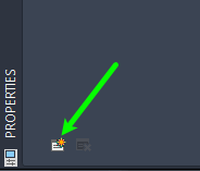
- Properties Palette > Extended Data tab
-
Click the Add Property Sets button in the bottom left corner
- From the Add Property Sets dialog, select the WetlandType property set > OK
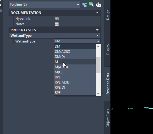
Assign the appropriate wetland types
Now that the objects have the WetlandType property set, the wetland type can be assigned. This property set works on polylines, feature lines, survey figures, and more.
- Select all boundaries of the same wetland type.
-
Properties Palette > Extended data: Assign the appropriate wetland type.
- Repeat for the remaining wetland boundary objects.
Add Wetland Labels
After the wetland objects have the wetland type property set assigned, the objects can be labeled.
-
Annotate tab > Add Labels
- Feature: Line and Curve
- Label Type: Single Segment
- Line Label Style: Wetland
- Curve Label Style: Wetland
- Add
- Select the objects to place labels
- After placement, adjust the location of the labels for best viewing, or leave as is.
Drawing clean up
After migrating all objects to appropriate layers and display styles, the unused components can be purged from the drawing
- Command line: PU
- Purge all unused components (Layers, Linetypes, blocks, etc)
- Save the drawing.