Attach an ortho image to a DWG using Map Connect
Last updated: 2026-01-06
The WisDOT coordinate projection zone category which was in use through Civil 3D 2016 and 2018 has been retired and is no longer needed in Civil 3D 2020 and beyond.
Coordinate systems in Civil 3D should only be applied when a projection transformation is needed.
Projections for Civil 3D 2020 and beyond should be selected from the Zone Category: USA, Wisconsin. WISCRS projections begin with NSRS2011 Wisconsin County CRS
Projections for Civil 3D 2016 and 2018 should be selected from the Zone Category: WisDOT.
There are multiple ways to bring in imagery files into Civil 3D. Sometimes these files will not plot correctly.
Warning: MAPIINSERT should be avoided. It can cause shifts in plots that will not manifest until plot time (i.e. looks good in modelspace, looks good in paperspace, pdf/hardcopy shifts). Any large image that requires a rotation in the viewport, that is aligned with a linear object is a good candidate to show this problem.
The following workflow is recommended to minimize issues related to plotting ortho-imagery files.
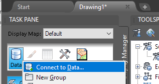
- MAPWSPACE Enter
- MAPWSPACE Task Pane <On>: Enter
-
TASK PANE > Display Manager tab > Data > Connect to Data...
- Data Connections by Provider: Add Raster Image or Surface Connection
- Navigate to desired image.
-
Open File
Warning: An image will not connect if the name of the image file has a comma (,) in it. Rename the image file, replacing any commas with underscores (_) before attempting to add a new connection.
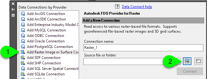
- Connect
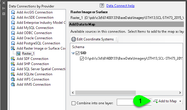
- At this point, an image can be reprojected if it's projection is different than the DWG. See Working with spatially referenced DWG, image, and GIS files for steps to reproject.
-
Add to Map