Infraworks: Component roads
Last updated: 2022-12-13
Total time: 31:35
 Draw a component road
iwx-lvl02-cmpnent-rd-01.mp4 3:51
Component roads are an advanced road option in InfraWorks that gives the users engineering design capabilities. Features such as roadside grading, cross slopes of lanes, super elevation, or curve radius based on traveled speed. The ability to calculate quantities from a component road is also an option. A component road gives us the ability to edit on multiple levels, such as the lanes, shoulders, and medians.
- Open model
- Ribbon > Create tab > Transportation panel > Component Road
- Road Properties data card
- Name: Component Road A
- Radio selected PI based
- Assembly: change to Four Lane Undivided
- On the model, left-click at start point, continue selecting points along the path to the end point, double-click at end point to close.
- Select road
- Road Properties data card
- Attributes - Such as function, set speed, add/remove lane markings
- Grading - Such as cut/fill material, cut/fill slopes
Converting a planning road to a component road
- Select planning road > right-click menu > Convert to Component Road
Adding and swapping components
iwx-lvl02-cmpnent-rd-02.mp4 6:34
- Adding component, shoulder
- Select component road > right-click menu > Insert Road Component
- Select template dialog box
- Select Shoulder
- A yellow line represents the placement of the new component
- Left-click the north side of the road to place the shoulder
- Use grips to widen the shoulder
- Drag middle grip point to the start grip to remove transition, repeat other side
- Edit the station number, manually key in number
- Select start or end point and set the station to align with Start of Road and End of Road
- Shoulder Properties data card
- Under Type, change the shoulder's material style
- Under Geometry, change the width, depth, or slope of the shoulder
- Swapping component, shoulder to jersey wall
- Select shoulder > right-click menu > Replace Component
- Select Component Style dialog box
- Select Jersey Barrier
- OK
Adding decorations
iwx-lvl02-cmpnent-rd-03.mp4 4:55
Besides lanes and shoulders, component roads will allow additional features to be added to it like street lights, power poles, and guard rails. These features are known as decorations. These decorations can be given a start location, spacing and then a potential horizontal or vertical offset from its insertion location
- Add guard rail
- Select component road > right-click menu > Place Decorations
- Select Component dialog box
- Select Guard Rail Straight
- Message: Pick a seam on the road to place decoration, then press Enter to finish.
- A yellow line represents the placement of the new component
- Select south side of the road
- Enter
- Select and edit guard rail
- Decoration Properties data card
- Name: rename
- Geometry
- Spacing: 9.8 , to place them close together
- Rotate: 180 , to rotate to face inside the road
- Other adjustments include horizontal or vertical offsets and scaling
- Decoration Properties data card
Roadside grading
iwx-lvl02-cmpnent-rd-04.mp4 5:06
Roadside grading with component roads allows different slopes to be applied from one side of the road to the other. It is possible to also have different side slope on the same side of the road with a transition area to blend the two areas together.
- Add grading
- Select component road
- Road Properties data card
- Grading
- Grading Method: Fixed Slope
- Cut Material > More Styles > Color > GreenOK
- Fill Material > More Styles > Color > BlueOK
- Grading
- Message: Hit Enter or click away from card to regenerate the section.
- Left-click inside the model window
- Select grading on north side of the road
- Grading Properties data card is specific to that grading
- Cut Slope: 1.00:1
- Fill Slope: 1.00:1
- Enter to update
- Add a transition
- Select grading > right-click menu > Split Grading
- Either left-click a point or key in station value
- Repeat so there are 3 sections
- Select middle section
- Grading Properties data card
- Cut Slope: 3.00:1
- Enter to update
- Select section to the right > right-click menu > Add transition
- Either left-click a point or key in station value
Superelevations
iwx-lvl02-cmpnent-rd-05.mp4 1:58
Component Roads can display the transition areas for superelevation as it enters and exits the curve. The Max Slope, Runoff for Tangent, and Spiral can be set within the properties of the road.
- View superelevation
- Select component road
- Road Properties data card
- Attributes > Superelevation toggle on
- Left-click inside the model window to update
- Select center line of road > right-click menu > check box Show Superelevation
- Road Properties data card
- Superelevation Input includes Max Superelevation Rate, Runoff on Tangent, and Runoff on Spiral
Cross section display
iwx-lvl02-cmpnent-rd-06.mp4 3:26
Display cross sections in three different views.
- Select road > right-click menu > Show station in Cross Section view
- Road Cross Section dialog box
- Station number box: use + or - to change the station
- A yellow line appears on the model to show where the cross section is. Right-click and drag to change location.
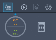
- Click
 to switch between Superelevation, Road Assembly, and Cut/Fill views of the roadway cross section.
Advanced road options
Bottom of the Road Properties data card, are advanced options.
- Select Earthwork Quantities (Cut/Fill) icon to preform calculations
- Earthwork Quantities dialog box
- Enter station ranges and turn on toggle
- Return to data card and select Play button to compute
- Calculates Cut, Fill, and Net Fill quantities
- Earthwork Quantities dialog box
- Select Materials Quantities (Calculator) icon
- Material Quantities dialog box
- Enter station ranges and turn toggle on
- Report calculates the length (ft.), area (sq.ft.), and volume (cu.yd) for each component of the road. This can include components such as jersey walls, light poles, trees, etc.
- Generate Report to generate a .CSV file.
- Material Quantities dialog box
Splitting components
iwx-lvl02-cmpnent-rd-07.mp4 3:41
When the design of the road is not typical from one end to the other it may be required to split apart your road components to add in the necessary detail.
- Create opening
- Select component barrier > right-click menu > Split Component
- Message: Key in a station value and press Enter, or click at a road station.
- Select component barrier > right-click menu > Split Component
- Message: Key in a station value and press Enter, or click at a road station.
- Select the middle section > right-click menu > Delete Component
- Modify opening
- Select shoulder > right-click menu > Split Component
- Snap point to station
- Select shoulder > right-click menu > Split Component
- Snap point to station
- Shoulder Properties data card > Geometry
- Width: 10.0'
- Add transition
- Select barrier's end grip point and move to allow room for transition
- Message: You have one or more edits on the component. Click outside of the component to refresh.
- Select shoulder > right-click menu > Transition In
Importing component roads into the library
iwx-lvl02-cmpnent-rd-08.mp4 2:04
Once a typical cross section has been created that area of the component road can be extracted and added the library for quick access. It is better to start with something that is similar then it is to start with a clean slate.
- Add a typical cross section to the library
- Select component road > right-click menu > Road Assembly > Add to Library
- Message: Key in a station value and press Enter, or click at a road station.
- Add to Library dialog box
- Type in a name and OK
- Use cross section to create a new road
- Ribbon > Create tab > Transportation panel > Component Road
- Road Properties data card
- Type > Assembly > Select the name of the assembly (blue hypertext)
- Select Assembly dialog box
- Select the new cross section
- Draw new road on model