Ground clearance analysis
Last updated: 2026-01-06
Total video time: 23:18
Exercise data: swept-pth-grnd-clrnc-data-C3D18.zip
 Setup drawing and create 2D swept path
swept-pth-grnd-clrnc-01.mp4 6:38
Create GroundClearance.dwg
- C3D App menu > New > Drawing
- Use wisdotXX.dwt template to create the new dwg file
- Save to the ProjectID\Design\Design Checks folder in the Civil 3D project
- Name the drawing GroundClearance.dwg
- Xreference project mapping and/or project edgelines
- Data Reference the surface to check
- Create a new surface called GC. GC stands for Ground Clearance. Paste the surface to be checked into the GC surface.
Select the DST Lowboy vehicle in the WisDOT Library
- AutoTURN/AutoTURN Pro 3D tab > Configure panel > Vehicles
- Group Vehicles By: Library
- Library selected: WisDOT
- Vehicle Name selected: DST Lowboy
- OK
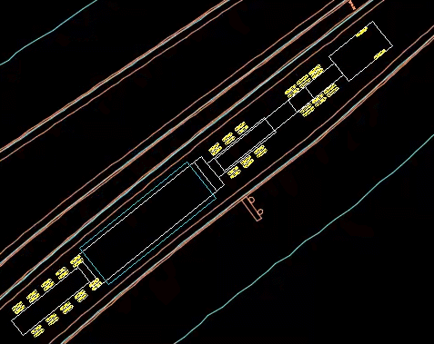
Create 2D swept path
Tip: Set layers simulation objects will be created on. This is not required, but a good practice.
- AutoTURN/AutoTURN Pro 3D tab > Configure panel > Properties
- Select Category: General (2D Simulations)
- Draw Path On, New Layer: AT-DSTLowboy
- Select Category: Vehicles (2D Simulations)
- Draw Path On, New Layer: AT-DSTLowboy-Veh
- Select Category: Envelopes (2D Simulations)
- Draw Path On, New Layer: AT-DSTLowboy-Env
- Select Category: Envelopes (2D Simulations)
- Draw Path On, New Layer: AT-DSTLowboy-Hatch
- OK
- Select Category: General (2D Simulations)
-
AutoTURN/AutoTURN Pro 3D tab > 2D SmartPaths panel > 2D Arc Path
Tip: Make sure to place the vehicle so that it fits entirely on the GC surface.
- Left click to place vehicle in start location
-
Left click to set orientation, or Apply angle in dialog box
-
Drag and click points through the swept path
Tip: It's a good idea to create multiple swept paths to check different possibilities for navigating the swept path. Different swept paths should be placed on different layers.
- Right click to finish simulation
-
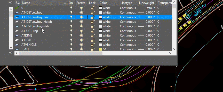
Home tab > Layers panel > Layer Properties
Review swept path layers and functionality. Different items can be frozen/thawed individually.
3D swept path
swept-pth-grnd-clrnc-02.mp4 4:01
Convert 2D to 3D
- AutoTURN/AutoTURN Pro 3D tab > Configure panel > Properties
- Select Category: General (3D Simulations)
- Draw Path On, New Layer: AT-DSTLowboy-3D
- Select Category: Vehicles (3D Simulations)
- Draw Path On, New Layer: AT-DSTLowboy-3D-Veh
- Select Category: Envelopes (3D Simulations)
- Draw Path On, New Layer: AT-DSTLowboy-3D-Env
- Select Category: Envelopes (3D Simulations)
- Draw Path On, New Layer: AT-DSTLowboy-3D-Hatch
- Select Category: Conflict Analysis
- Draw Conflict Analysis On, New Layer: AT-DSTLowboy-Conflict
- OK
- Select Category: General (3D Simulations)
- AutoTURN Pro 3D tab > 3D > Select Terrain
- Surface Name: GC
- Use
- AutoTURN Pro 3D > 3D > Convert 2D to 3D
- Pick a 2D turn simulation Click 2D swept path in modelspace
-
Would you like to delete the 2D Simulation? NO
Warning: When prompted, choose whether to delete the 2D simulation. We recommend not deleting the simulation so it is available for later use.
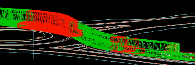
There are some red hatch areas where there are conflicts, but the 3D simulation did not show up. We will turn on the 3D simulation in the next step.
- AutoTURN/AutoTURN Pro 3D tab > Configure panel > Properties
- Select Category: Envelopes (3D Simulations)
- Vehicle Body: checked
- Update
- Pick any element in a turn simulation to update it Click simulation in modelspace
- Ok
- Select Category: Envelopes (3D Simulations)
- Quick Access Toolbar > Save
-
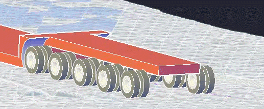
Orbit model to view in 3D
Return to top view
- Home tab > Layers panel > Layer Properties to turn on/off 3D simulation objects same as the 2D objects.
Punch throughs
swept-pth-grnd-clrnc-03.mp4 7:07
Create punch through at specific areas of concern
Info: Punch throughs are essentially cross sections
- Home tab > Draw panel > Line tool
- Draw lines at locations of where you want to create a punch through. Can be in any direction. The line needs to go through the entire swept path. We will analyze a few conflict areas.
- AutoTURN Pro 3D > Analyze > Punch Through
- Pick a 3D turn simulation
- Pick a line to create a punch through and report
- Place punch through report in the drawing
-
Analyze Punch Through (see image for recommended settings)
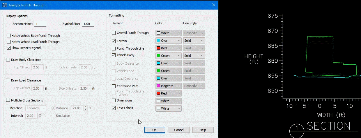
Tip: Dimensions do not always end up where you may want them. We recommend using Civil 3D dimension tools.
OK
- Repeat step 2 for other lines, changing the Section Name for each.
Create multiple punch throughs
- Home tab > Draw panel > Line tool
- Draw one line at the first location where a punch through is desired
- Measure the distance forward to create multiple punch throughs
- AutoTURN Pro 3D > Analyze > Punch Through
- Pick a 3D turn simulation
- Pick a line to create a punch through and report
- Place punch through report in the drawing
- Analyze Punch Through
- Section Name: 4
- Multiple Cross Sections: checked
- Direction: Forward
- Distance: 70 ft
- Interval 2 ft
OK
An array of punch throughs will be created
- WisDOT Sheets tab > WisDOT Annotation panel > Dimension to check conflict amount
Warning: Punch throughs are not dynamic to the lines, simulation, and surface that created them. New punch throughs need to be created if anything changes.
3D Animation
swept-pth-grnd-clrnc-04.mp4 3:16
Create 3D animation
- Orbit to desire point of view
- Home tab > Layers panel > Freeze
- Select punch throughs in modelspace
- Home tab > Layers panel > Layer Properties
- Freeze AT-DSTLowboy-Conflict
- Click surface Ex in modelspace to select it
- Contextual ribbon > Modify panel > Surface Properties
- Information tab > Surface Style: Pavement Triangles
- OK
-
View > Visual Styles > View Styles dropdown > Conceptualto see the simulation better in 3D
- AutoTURN Pro 3D > Visualize > Animate
-
Pick a Simulation or Path in the Drawing
Tip: The 3D arrow markers along the path work best for this.
-
- Run Animation Dialog
- Hide Simulation: checked to turn off swept path display.
Drag slider to drive vehicle along path
Info: There are options for recording an animation from different view perspectives.
- Close
- View tab > Visual Styles panel > View Styles dropdown > 2D Wireframe
-
View tab > View panel > Top
Switch existing surface to design surface
swept-pth-grnd-clrnc-05.mp4 2:15
The following steps will switch the existing surface with a design surface in the ground clearance surface.
- Toolspace > Prospector > Data Shorcuts > Surfaces > Refinement > Click and drag Rfnt-CrwndCircRdwy into modelspace to data shortcut reference the revised design surface
- Toolspace > Prospector > Surfaces > GC > Right click Edits > Paste Surface...to paste the new surface into the GC surface
- Click Rfnt-CrwndCircRdwy
- OK
- Toolspace > Prospector > Surfaces > Right click GC > Properties
- Definition tab > Paste Add surface Ex: unchecked
- OK
Regenerate Simulation
- AutoTURN Pro 3D > Edit panel > Regenerate Simulation
- Pick a Simulation in the Drawing
Recheck Ground Clearance
Warning: Punch throughs are not dynamic and need to be redone