Civil 3D release comparison 2016 to 2018
Last updated: 2026-01-06
 New file format in Civil 3D 2018
Info: Traditionally, AutoCAD changes its DWG file format after three versions. AutoCAD 2017 will be the first version to keep the same DWG format (AC1027) for over four years. This DWG format has been used since the AutoCAD 2013 release. 2018 will be a new file format.
Warning: AutoCAD Civil 3D 2018 is not backward compatible! You can save a 2017 or earlier drawing to 2018 and you will be able to use all Civil 3D objects as normal; but after that drawing is saved in Civil 3D 2018 format and you try to open it in Civil 3D 2016 or earlier you will get the following message:
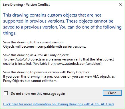
If you click OK, the Civil 3D objects will be transformed into proxy objects, which basically means profiles, alignments, and surfaces will be more like a block. You will lose the ability to edit and update them using Civil 3D tools.
Why Did This Happen?
Although the DWG format did not change, Autodesk made the decision to update their objects for the 2017 release with custom and AEC objects of vertical and 3rd party products. This will hopefully enable them to implement improvements in the initial release, as well as provide the platform with some new features on the horizon.
How Does this Affect Me?
Since Autodesk subscription allows you to download and install up to 3 previous versions of Civil 3D, this shouldn't affect you if you use the appropriate software that your projects call for.
If you are working on a project in earlier releases, keep the files with those versions until you are ready to move the entire project in the newest version. Just be prepared for when you save a file in the Civil 3D 2018 format; plan on keeping it there.
AutoCAD 2018-based products use a different drawing format than AutoCAD 2017-based products and earlier. When sharing drawing files with users on AutoCAD 2017-based products or earlier, you will need to save your drawings to the appropriate drawing file format using the SAVEAS command or another method.
To open AutoCAD Civil 3D 2018 drawings and view the AutoCAD Civil 3D objects in a prior version of the software, set the PROXYGRAPHICS system variable value to 1 in AutoCAD Civil 3D 2018 to save the graphics with the drawing and then use the Save As command to save the drawing to a prior drawing file format. When you open the drawing in a prior version of the software, the AutoCAD Civil 3D objects will be displayed as proxy graphics.
Interoperability Between AutoCAD Civil 3D 2018 & 2018.1
Warning: With the roll out of WisDOT Civil 3D 2018 all WisDOT computers will be working in the 2018.2 version of Civil 3D. However there may be some contractors who do not have the service pack installed who may experience these issues. Best practices would be to install the latest version and service packs.
This topic describes how to open an AutoCAD Civil 3D 2018 drawing and view the AutoCAD Civil 3D objects in a prior version of the software. It also describes interoperability between AutoCAD Civil 3D 2018 & AutoCAD Civil 3D 2018.1.
Opening an AutoCAD Civil 3D 2018 Drawing in a Prior Version of AutoCAD Civil 3D
Drawings saved in AutoCAD Civil 3D 2018 use the AutoCAD 2018 drawing file format and must be saved to a prior drawing file format before they can be opened in a prior version of the software.
To open AutoCAD Civil 3D 2018 drawings and view the AutoCAD Civil 3D objects in a prior version of the software, set the PROXYGRAPHICS system variable value to 1 in AutoCAD Civil 3D 2018 to save the graphics with the drawing and then use the Save As command to save the drawing to a prior drawing file format. When you open the drawing in a prior version of the software, the AutoCAD Civil 3D objects will be displayed as proxy graphics.
Interoperability Between AutoCAD Civil 3D 2018 and AutoCAD Civil 3D 2018.1
Rehab Corridors
- If you open and save a drawing in AutoCAD Civil 3D 2018 that contains a rehab corridor created in AutoCAD Civil 3D 2018.1, and then re-open the drawing in AutoCAD Civil 3D 2018.1, the rehab corridor will not be affected and will appear as it was created.
Tip: You can also make edits to anything other than the rehab corridor in the drawing in AutoCAD Civil 3D 2018 without affecting the rehab corridor when the drawing is re-opened in AutoCAD Civil 3D 2018.1.
- If you make an edit to a rehab corridor and it is rebuilt in AutoCAD Civil 3D 2018, the rehab corridor regions will disappear. If you save the drawing, when you re-open the drawing in AutoCAD Civil 3D 2018.1 the rehab corridor regions will not appear. To restore the rehab corridor regions, ensure that the rehab subassemblies have been imported in AutoCAD Civil 3D 2018.1, and then make an edit to the corridor and rebuild it.
Tip: The rehab subassemblies are imported automatically when you run the CreateRehabCorridor or EditRehabCorridor commands if they have not already been imported. You can also import the rehab subassemblies by using the AeccImportNewRehabContent command.
Projections and Crossings
- Linear objects that cross a sample line and are projected to section views in a AutoCAD Civil 3D 2018 drawing will be displayed as crossings when the drawing is opened in AutoCAD Civil 3D 2018.1.
Info: Because these linear objects will be displayed as crossings in AutoCAD Civil 3D 2018.1 instead of projections, projection labels that were added to the objects in AutoCAD Civil 3D 2018 will be converted to crossing labels after you open the Section View Properties dialog box and click Apply in AutoCAD Civil 3D 2018.1.
- Non-linear objects that are projected to section views in a AutoCAD Civil 3D 2018 drawing will be displayed as projections when the drawing is opened in AutoCAD Civil 3D 2018.1 and the Draw Crossings check box for those objects will be cleared by default on the Projections and Crossings tab of the Section View Properties dialog box.
- A 3D solid projection that represents the solid exactly where the sample line crosses it in an AutoCAD Civil 3D 2018 drawing will have the same appearance when the drawing is opened in AutoCAD Civil 3D 2018.1. However, in AutoCAD Civil 3D 2018.1, the 3D solid will be displayed as a crossing and <Section> will be selected as the crossing marker style on the Projections and Crossings tab of the Section View Properties dialog box. The Draw Projections check box for the 3D solid will be cleared by default.
Info: In previous releases, when AutoCAD Solids was selected on the Section tab in the Projection Style dialog box, the Section check box would appear. When the Section check box was selected for the projection style, the projection would be created to represent the solid exactly where the sample line crossed it. To replicate this appearance in AutoCAD Civil 3D 2018.1, select the Draw Crossings check boxes for the 3D solids on the Projections and Crossings tab of the Section View Properties dialog box (or in the Projections and Crossings Output Display Options dialog box), select <Section> as the crossing marker style, and clear the Draw Projections check boxes.
- A 3D solid crossing created in an AutoCAD Civil 3D 2018.1 drawing using the <Section> crossing marker style will be displayed as a projection when the drawing is opened in AutoCAD Civil 3D 2018 and will use either the As Drawn or Marker Style option in its projection style (depending on how the projection style it is assigned in AutoCAD Civil 3D 2018.1 is configured). To update the projection style in AutoCAD Civil 3D 2018 so that the 3D solid projection represents the solid exactly where the sample line crosses it, select AutoCAD Solids on the Section tab in the Projection Style dialog box, select As Drawn, and then select the Section check box.
- Crossing labels created in AutoCAD Civil 3D 2018.1 will be displayed as proxy objects if the drawing is opened in AutoCAD Civil 3D 2018 and they cannot be deleted. If the drawing is saved in AutoCAD Civil 3D 2018 and re-opened in AutoCAD Civil 3D 2018.1, they will be displayed as crossing labels.
- Projections and crossings that are hidden in a section view using AutoCAD Civil 3D 2018.1 will be shown if the drawing is opened in AutoCAD Civil 3D 2018. If the drawing is saved in AutoCAD Civil 3D 2018 and re-opened in AutoCAD Civil 3D 2018.1, they will be hidden.
Interoperability Between AutoCAD Civil 3D 2018.1 & 2018.2
Warning: With the roll out of WisDOT Civil 3D 2018 all WisDOT computers will be working in the 2018.2 version of Civil 3D. However there may be some contractors who do not have the service pack installed who may experience these issues. Best practices would be to install the latest version and service packs.
Vertical Curves in Offset Profile Slope Transition Regions
When opening a drawing with an offset profile in a different version of AutoCAD Civil 3D, the appearance of the offset profile in slope transition regions where vertical curves are present in the parent profile will be maintained until the offset profile is redrawn.
- To redraw an offset profile, open the Profile Properties dialog box, navigate to the Offset Parameters tab, and click OK or Apply.
Opening an AutoCAD Civil 3D 2018 or AutoCAD Civil 3D 2018.1 drawing in AutoCAD Civil 3D 2018.2
- The tangents that are used instead of vertical curves in an offset profile slope transition region are maintained.
- The tangents will be updated as vertical curves after the offset profile is redrawn in AutoCAD Civil 3D 2018.2.
Opening an AutoCAD Civil 3D 2018.2 drawing in AutoCAD Civil 3D 2018 or AutoCAD Civil 3D 2018.1
- The vertical curves in an offset profile slope transition region are maintained.
- The vertical curves will be updated as tangents after the offset profile is redrawn in AutoCAD Civil 3D 2018 or AutoCAD Civil 3D 2018.1.
3D Solid Crossing Appearance in Section Views
Opening an AutoCAD Civil 3D 2018.1 drawing in AutoCAD Civil 3D 2018.2
- The appearance of a 3D solid crossing that uses the <Section> crossing marker style will be derived from the layer associated with the 3D solid rather than by the projection style associated with the 3D solid.
Opening an AutoCAD Civil 3D 2018.2 drawing in AutoCAD Civil 3D 2018.1
- The appearance of a 3D solid crossing that uses the <Section> crossing marker style will be derived from the projection style associated with the 3D solid rather than by the layer associated with the 3D solid.
Corridors
Extracting solids from corridors
-
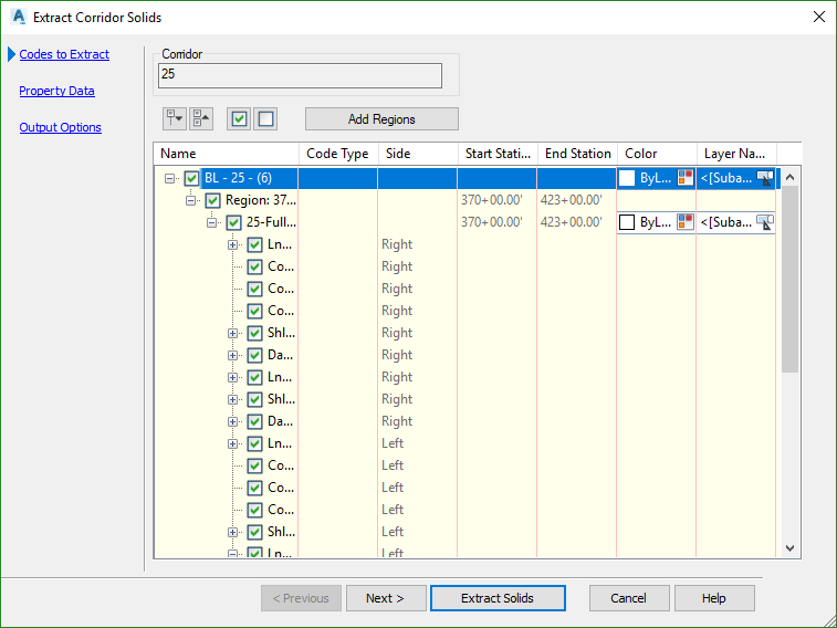
The process for extracting solids from corridors has been enhanced. New options are available for selecting the corridor areas to extract within corridor regions, station ranges, or closed polygonal areas. When created in the same drawing as the corridor or corridor reference, the solids can now be created with a dynamic link to the corridor so they update when the corridor is updated.
-
A Property Data page is now included in the wizard which you can use to automatically associate property data with the solids, such as corridor name, region name, and code name.

- For more information see To Extract Corridor Solids
Feature lines as corridor baselines
- In addition to alignments and profiles, you can now use feature lines as corridor baselines. You can select the feature lines when creating the corridor and when adding baselines. The feature lines that you can use can be created from the feature line creation tools. Corridor feature lines cannot be used directly but can be used if extracted from the corridor. For more information see: Adding Baselines to a Corridor to Create Offset Alignments
Corridor feature lines can cross a base line
- An option is now provided for controlling whether corridor feature lines can cross a baseline. For example, in certain situations, such as with a divided highway, part of a corridor design may need to cross the centerline and this can require that the corresponding feature lines also cross the centerline. For more information see: Feature Lines Cross Baseline
Corridor cleanup
- Where corridor tangents intersect at a corner, and where the corridor is created at a fixed width, the inner and outer corners of corridors are cleaned up automatically.
-
In AutoCAD Civil 3D 2018, where corridor tangents intersect at a corner, and where the corridor is created at a fixed width, the corners are cleaned up as follows: About Corridor Cleanup
Corridor Data Shortcuts
Create Corridor data shortcuts
You can now create data shortcuts for corridors so you can reference them into other drawings. When you create a data shortcut for a corridor, shortcuts are also created for the alignments and profiles that make up the corridor baselines. If corridor baselines are comprised of feature lines, shortcuts are not created independently for those feature lines. For more information see: To Work with Data Shortcuts and To Create Corridor References
Save the geometry of a reference
You can now save the geometry of a reference surface in the drawing that contains the data shortcut reference. If you choose to save the geometry of a reference surface in the drawing, the drawing that contains the reference will become larger, but will open more quickly unless the source surface has changed. For more information see: To Work with Surface References
Multiple data shortcut references
You can now create multiple data shortcut references at once, by either right-clicking the data shortcuts and selecting the Create Reference command, or by selecting them and dragging them into the drawing. This functionality is available from the Data Shortcuts collection in Prospector and in the Data Shortcut Manager dialog box. For more information see: Work with Data Shortcut References and To Manage Data Shortcuts
Control notifications
You can now control whether notifications appear at the drawing status bar when data shortcut references are out of date and need to be synchronized. For more information see: To Synchronize a Reference Object

Object Data and Shortcut Sub-folders
- You can now create sub-folders within Prospector and the Data Shortcut Manager. Right-click an object collection or a data shortcut collection and click Create Folder. You can drag-and-drop existing objects into the new folders, and you can place folders inside other folders. When you create references to data shortcuts that are stored in sub-folders, the sub-folder structure is replicated in the consumer drawing. For more information see: To Manage Data Shortcuts and About the Toolspace Prospector Tab
Roundabouts
From Autodesk Vehicle Tracking
The roundabout-related features from Autodesk® Vehicle Tracking have been integrated into AutoCAD Civil 3D. These commands create a new type of roundabout object. For more information see: About Roundabouts
From Autodesk Infraworks 360
You can now bring roundabouts into an AutoCAD Civil 3D drawing from Autodesk® InfraWorks® 360. For more information see: About Exchanging Data Between AutoCAD Civil 3D and Autodesk InfraWorks 360.
Design Efficiency
Relative Feature Lines
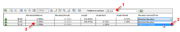
Create feature lines that are relative to surface. Feature line elevations can be obtained from a surface and can also be relative to a surface, so if the surface is updated, the feature line is updated.
-
Behavior of feature lines created to be relative to surface. If the surface is edited, the feature line is updated automatically

-
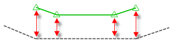
Behavior of feature lines created at fixed elevations, and then set to be relative. The following illustration shows a feature line that was drawn at fixed elevations with no relationship to the surface. If the surface below it is edited, the feature line elevations will not update.
-
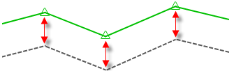
However, the relative elevation offsets between the feature line and the surface will now be maintained if the surface is edited, such as if the elevation is lowered, as shown in the following illustration.
-
Feature line editing commands are supported for relative feature lines. You can specify relative elevation options by using the following features in the Grading Elevation Editor.
-
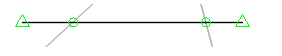
When you create a feature line and assign elevations based on a surface, you can select the Insert Intermediate Grade Break Points check box. This creates elevation points along the feature line where the feature line crosses surface TIN lines. These points are shown as green circles in the following illustration.
-
If you edit or otherwise move a relative feature line, or if the surface it is relative to is updated, elevation points are not automatically added or removed on the feature line to match the surface TIN lines, as shown in the following illustration.

- You can update the elevation points on the feature line by using the Insert Elevation Point and Delete Elevation Point editing options in the Grading Elevation Editor or on the Edit Elevations panel of the Feature Line ribbon tab.
Offset Profiles Relative to Alignment Baseline
- You can create dynamic offset profiles using the same command you use to create offset alignments. The profile geometry is offset using a default cross slope which you can modify by editing the profile properties

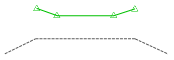
Tip: Vertical curves in offset profile geometry are tessellated as multiple straight segments as shown below when the profile is superimposed onto another profile view. For reviewing and editing the offset profile geometry, insert the offset profile into its own profile view by using the Create Profile View command and selecting the offset alignment.
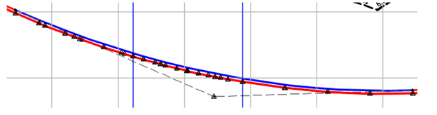
- In areas of the offset profile where there are vertical curves and there is a transition between one cross slope to another cross slope, as specified in the Offset Parameters tab of the offset profile properties, the vertical curve geometry that was replicated from the parent profile will not be preserved. Instead, straight lines are added between control points to approximate the curve as shown in the following illustration.

Intersecting Alignments and Transition Profile
- Create an alignment that transitions between two intersecting alignments and create a profile that transitions between their profiles
- The connected alignment is created between the two intersecting alignments at a specified radius.
- The geometry of the connected profile is automatically generated from the parent profiles that you select. The start and end elevations and slope are taken from the parent profiles, and the middle section of the connected profile is calculated depending on whether extensions of the parent profiles intersect.
- When you create a connected alignment and associated profile, by default they are set to dynamic state, which means that they will partially update if their parent alignments and profiles change. You can change the update mode to static if you want to prevent any updates from occurring and if you want full editing control over the alignment and profile.
Resolve Corridor Bowties
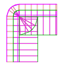
At some locations on corridor models, the corridor links can cross each other, resulting in bowtie-like configurations. The following illustration shows a corridor with a bowtie configuration at the corner.
Automatic and command-based corner cleanup
In some situations, such as where corridor tangents intersect at a corner, and where the corridor is created at a fixed width, bowties can be cleared automatically. You can control which types of bowtie intersections are cleared automatically by changing the Automatic Clear Bowtie Options in the Edit Feature Settings - Corridor dialog box.
In other situations, such as when the corridor is created at a variable width (such as when daylighting to a surface), you can use the Clear Corridor Bowties command.
The automatic AutoCAD Civil 3D corridor cleanup behavior can be applied at tangent-tangent, tangent-curve, and tangent-curve-tangent intersection locations in corridors that use feature lines or alignment/profiles as baselines, and the assemblies have consistent widths as set by shapes within the assembly.
For example, where corridor tangents intersect at a corner, and where the corridor is created at a fixed width, the corners are cleaned up as follows:
- The point where the inner corners meet is calculated and radial lines are extended from that location, using the insertion frequency along the baseline as defined in the Frequency to Apply Assemblies dialog box.
- In addition, one station is also added at the corner if the At Horizontal Geometry Points option is selected in the Frequency to Apply Assemblies dialog box:
- The subassembly width value is overridden at the radial stations; the width is calculated to produce a corner solution that is similar to the AutoCAD Offset command.
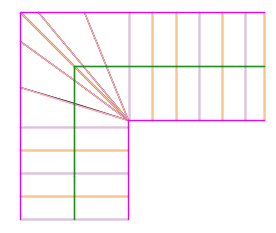
- The following illustration represents a corner prior to clearing the bowtie. The corridor baseline is shown in red.
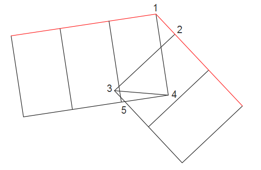
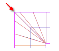
- The following illustration represents a corner after clearing the bowtie.

- Points 3 and 4 are moved to the location of point 5, and the elevation of point 4 is now used in that location. The locations and elevations of points 1 and 2 are unchanged.
Model, assess, and optimize rehab corridors for roadway rehabilitation projects.
-
When creating a rehab corridor, you specify parameters for cross slope correction, mill, level, and overlay, and AutoCAD Civil 3D builds the assembly and the corridor to meet your specified criteria.

-
Based on the parameters you specify when creating a rehab corridor, the assembly for the corridor is built automatically using the following subassemblies:

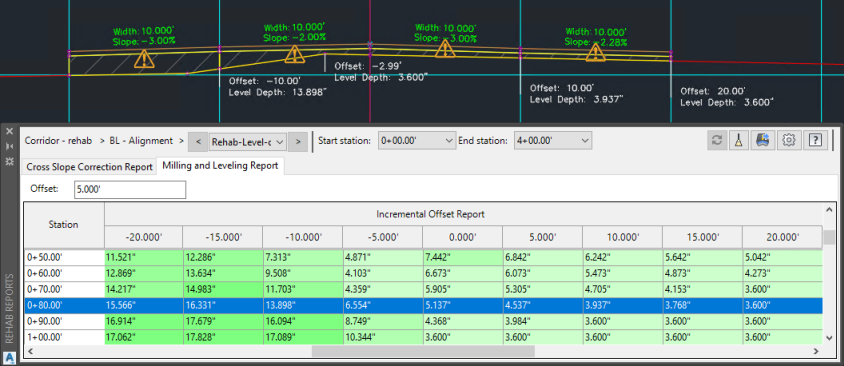
Generate Rehab Corridor Reports.
-
You can use the Rehab Manager to generate Cross Slope Correction and Milling and Leveling reports for selected stations within rehab corridor regions. You can make changes to values in the reports, and apply the changes back to the rehab corridor.
Set Width or Offset Target Dialog Box.
- Specify whether to use targets on the same side of the baseline as a subassembly or on either side of the baseline. When you are setting up subassembly targets, you can select the Use Targets On the Same Side As the Subassembly check box in the Set Width Or Offset Target dialog box to use targets on the same side of the baseline as the subassembly. You can clear this check box to use targets on either side of the baseline.
Production Efficiency
Section Views and Sheet Layout
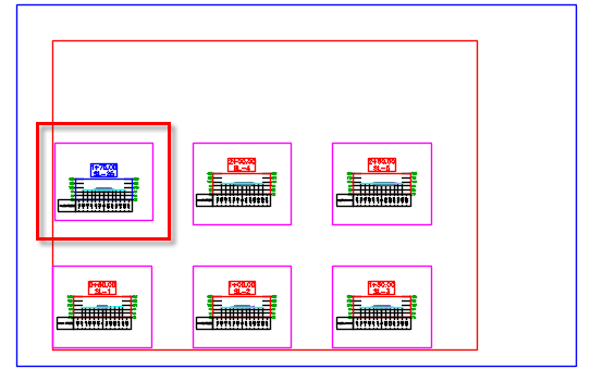
Move section views between section view groups:
- The section views that you want to move and the destination section view group must share the same sample line group.
- Section views can be moved from the individual section views collection to a section view group, or from one section view group to another section view group.
- The section views are inserted into the section view group in order of their stationing. They are inserted between existing section views in the group as needed so all the section views are in order.
- If the styles are different, the section views you are moving can keep their existing styles, or they can use the style of the destination section view group.
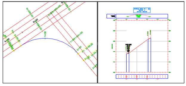
- In the following example, an individual section SL-25 needs to be moved into the section view group. Its station is 1+75 so it will be inserted between the sections for station 1+50 and 2+00.
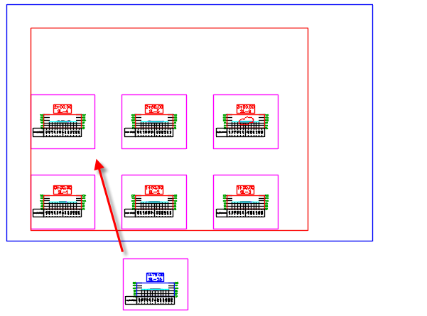
- The following illustration shows the section view inserted into the section view group. You can choose to keep the existing stylization, as shown in this example, or you can choose to apply the stylization of the destination section view group to the moved sections. The section view for station 3+00 was moved to the next sheet.
Update the sheet layout
- When updating the section view sheet layout, resized or inserted section views are respected. You can update the layout of a section view group to reset the location of section views that were moved out of place, or to update the layout due to another change, such as a change in a style or the change in the size of a section or of a drafting buffer. For example, in the following illustration, the bottom edge of the drafting buffer of the top-middle section was increased to accommodate the additional annotation below the section view.
- You can run the Update Group Layout command to reset the layout so that the minimum row height is applied to the layout, as follows.

- Select a section view whose group layout needs to be updated.
- Click Section tab>Modify View panel>Update Group Layout > Find.
- The layout of the section view group is updated to reflect any changes.
Section View Drafting
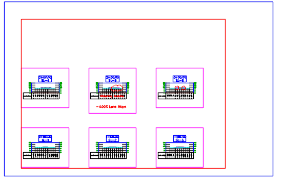
- Manage section view annotation by adding it within or crossing the section view drafting buffers. Annotation and drafting elements that you add within or crossing the section view drafting buffers will be bound to the section views and will move along with the section views. Section views are created with drafting buffers. When you add AutoCAD annotation or drafting elements or AutoCAD Civil 3D note labels within or crossing the drafting buffers, they are bound with the section views, and are moved with the section views if they are moved. In the following illustration, the drafting buffers around the section views are shown in magenta. Drafting elements that were added to the sheet are shown in red.
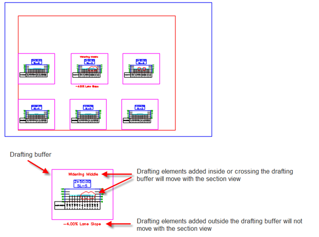
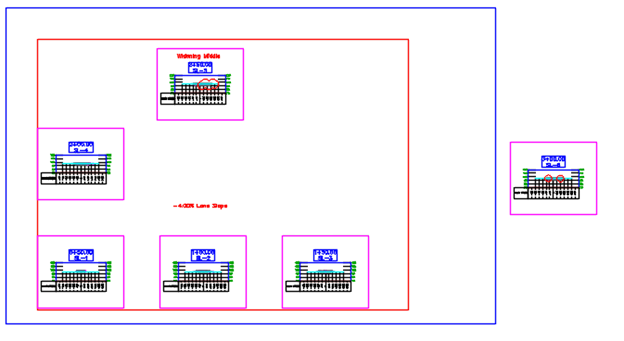
- When the section views for station 2+50 and 3+00 are moved up or off the sheet, the drafting elements that are inside the drafting buffers are moved with the section views. The text that notes the lane slope is not moved because it was outside the drafting buffer area.
Binding drafting elements with a section view
- Drafting elements become bound to a section view when there are added or modified within or crossing the drafting buffer.
- Any new or existing drafting elements that are added or moved within or crossing a drafting buffer become bound to the section view.
- If you make a drafting buffer larger to encompass or cross existing drafting elements, those drafting elements become bound to the section view after you make an edit to them.
- If you make a drafting buffer smaller, drafting elements that were previously inside or crossing the drafting buffer remain bound to the section view until you make an edit to them.
Use enhanced options for working with projections and crossings in section views.
- You can display and label the locations where objects cross a sample line using options that are specifically for crossings.
-
When projecting objects to multiple section views, you can use options for filtering the selection of objects by layer, style, and point group.
-
You can now project objects to a section view from plan view by using a command on the sample line context menu.
-
You can now hide projected objects without removing the objects from the section views by using check boxes on the Projections tab in the Section View Properties dialog box.
-
Additional options have been added for controlling the label styles for projected objects and crossing objects in section views.
Tip: Now you can change the label styles after the objects have been projected.
To Navigate Between Sample Lines and Section Views.
- Use new navigation options to zoom to a section view from a sample line, and to zoom to a sample line from a section view.
Drafting buffer grips
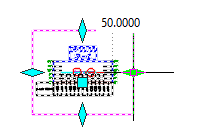
- You can use the grips on a drafting buffer to increase or decrease its size. The following illustration shows the grips and the value of the right drafting buffer margin (50.0000) when you hover over that grip. You can select the grip and drag it to resize the drafting buffer, or you can and enter a new value at the command line.
- Resizing a drafting buffer after drafting elements already exist does not automatically change the binding behavior of the drafting elements relative to that drafting buffer. For more information about the binding behavior, see "Binding drafting elements with a section view" above.
Plan/Plan and Profile/Profile Sheets
- Create plan/plan and profile/profile sheets by including multiple plan or profile views on a single sheet. New drawing templates have been provided that have their viewports already configured for these sheet layout types, which you can select when laying out the view frames.
Add Property set data to labels
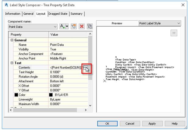
- Open the Label Style Composer by creating or editing a label style for the project.
- In the Label Style Composer dialog box > Layout tab
- Select an existing component from the Component Name list, or add a new component for the label text.
-
Under Text, click in the value column for contents > OK
-
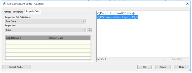
In the Text Component Editor dialog box, click the Property Sets tab.
Info: The Property Sets tab will not appear in the Text Component Editor if there is no property set applied to the relevant object type.
- Select the property set definition to use and the property to insert.
-
Click the arrow to insert the property into the text window. In the following example, the Type property has been added to the label style after the point number.
- After adding each property into the text window, click in the window and press Enter to insert a paragraph return
-
Add static text as needed in the Text Component Editor window, such as "Condition" or "Tree Height". To do this, click in the Text Component Editor window and enter the text directly.
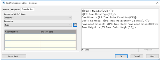
- OK
Traverse Editor
Traverse Editor:
- Input and edit traverse data. Create points, lines, and curves representing traverse legs and sideshots using COGO input and editing tools. The traverse can be used to generate a polyline, COGO points, and a TRV2 traverse file which you can open in the Traverse Adjustment dialog box and apply an adjustment method. For more information see: To Input Traverse Data in the Traverse Editor
Traverse Adjustment:
- Apply an adjustment method to traverse data. Perform traverse adjustments and generate reports using Compass, Transit, Crandall, and Grant Line adjustment methods, and update COGO points and traverse geometry within the drawing. For more information see: To Adjust Traverse Data